
RCDD-112 · Lesson 10 of 12 · 25 min
Power over Ethernet and cabling heat
▶ Video coming soon A video version of this lesson is on the way.
Priya Raman, the electrical engineer for Harborview, sends Roz a note: the lighting designer wants to power every light fixture in the third-floor classrooms over Ethernet, 210 fixtures, each drawing up to 40 watts. Priya's question is simple. Who is designing the power distribution for those lights, the electrical engineer or the cabling designer? Roz's answer is both. Once the cabling carries significant power, it becomes part of the building's power system, and the cabling designer must understand power, heat and the codes that govern them.
How Power over Ethernet works
Power over Ethernet sends direct current along the same twisted pairs that carry data. The power sourcing equipment, usually a network switch or a midspan injector, applies a voltage between pairs, and the powered device at the far end, such as an access point, camera, phone or light fixture, draws current. Before applying full power, the equipment detects a valid powered device and classifies how much power it needs, so ordinary network devices are never harmed. Power and data share the conductors without interfering, because the power is applied as a common voltage on both wires of a pair, which the data transformers ignore.
The IEEE 802.3 standards define the power types. The original standard, now called Type 1, delivers up to 15.4 watts at the switch port over two pairs. Type 2, often called PoE+, delivers up to 30 watts over two pairs. The later standard 802.3bt added Type 3, up to 60 watts, and Type 4, up to 90 watts, both using all four pairs. Some vendors sell proprietary systems at higher levels, but the IEEE types are what designers plan around.
| IEEE type | Common name | Pairs used | Power at the switch port | Power at the device, worst case |
|---|---|---|---|---|
| Type 1 | PoE | 2 | 15.4 W | 12.95 W |
| Type 2 | PoE+ | 2 | 30 W | 25.5 W |
| Type 3 | 4-pair PoE | 2 or 4 | 60 W | 51 W |
| Type 4 | High-power PoE | 4 | 90 W | 71.3 W |
Where the power goes
The difference between the power at the switch and the power at the device is lost in the cabling as heat. The standards assume a worst-case 100 meter channel with a set loop resistance, and the device is guaranteed the lower figure even in that worst case. For Type 4, that means up to 18.7 watts lost in a single cable, about 0.19 watts per meter. In a short, cool channel, less is lost, but designers plan for the worst case because they do not control what will be connected later.
The heat comes from the resistance of the copper. Power lost in a conductor is the square of the current times the resistance, so doubling the current quadruples the heat. That is why higher PoE types use all four pairs: spreading the current over more conductors reduces the current in each and the heat generated. It is also why conductor gauge matters. A 22 or 23 AWG conductor, common in Category 6A cable, has less resistance than a 24 or 26 AWG conductor and heats less at the same current.
Heat in bundles
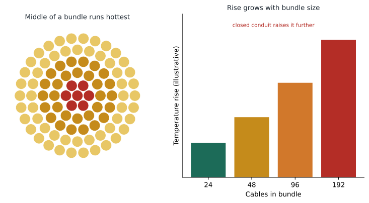
A single cable carrying PoE in open air loses its heat easily. A bundle of many such cables cannot, because the cables in the middle are surrounded by other warm cables. The temperature in the center of a large bundle rises above the surrounding air, and that rise grows with the number of cables, the current in each, the tightness of the bundle and whether it is enclosed in conduit, insulation or a closed tray. TIA's guidance on supporting remote powering, TSB-184-A, studied these effects for currents up to 1000 milliamperes per pair. It recommends Category 6A or higher for new installations that will carry power, and suggests keeping bundles small, about 24 cables, or leaving cables unbundled in open trays where possible.
Temperature matters for two reasons. Cable jackets and insulation are rated for a maximum operating temperature, commonly 60 or 75 degrees Celsius, and a bundle in a hot ceiling with high current can approach that rating. And, as lesson 7 showed, insertion loss rises with temperature, so a hot bundle may stop supporting its data application even if the cable is not damaged. The designer must plan for both: the safety limit set by the code and the performance limit set by the channel.
What the codes say
Power over Ethernet is limited-energy power, but the codes still govern it. The NEC treats PoE as Class 2 or Class 3 power. Since the 2017 edition, section 725.144 limits the current in bundles of 4-pair cables carrying power above 60 watts, with a table that depends on the conductor gauge, the temperature rating of the cable and the number of cables in the bundle. Cables marked with the limited-power suffix LP, such as CL2-LP or CMP-LP, are listed to carry a stated current per conductor and can simplify compliance. Code requirements are set for safety; the cabling standards add performance guidance. Both apply.
Connectors under power
When a patch cord is unplugged while power is flowing, a small arc can form between the jack and plug contacts as they separate. Over many cycles, the arc can damage the contact surfaces where the plug wipes the jack at full insertion. Connectors designed for powered use are tested to an international standard for this, IEC 60512-99-001 and its later revisions, and manufacturers publish which products comply. Designers should specify compliant connectors at the patch panel and at outlets that will carry high power, and operational procedures should prefer turning off port power before moving a cord.
Design steps for powered cabling
Roz and Daniel follow six steps for the powered parts of Harborview. First, list the powered devices and their PoE type: access points at Type 3, cameras at Type 2, lights at Type 3, a few displays at Type 4. Second, choose Category 6A cable of a construction suited to remote powering, and connectors rated for unmating under power. Third, plan pathways that keep bundles small and open: cable trays rather than conduit where possible, several smaller bundles rather than one large one, and no runs through thermal insulation. Fourth, check the code limits for the bundle sizes and cable ratings chosen. Fifth, check the effect of the highest expected temperature on insertion loss. Sixth, size the switch power supplies and the telecommunications room's electrical and cooling capacity for the total PoE load.
That last step is easy to forget. Power delivered over Ethernet starts as alternating current at the switch power supply, and every watt delivered to lights in the ceiling is a watt drawn from the telecommunications room circuits. The losses in the cabling end up as heat in the ceilings, and the losses in the switch end up as heat in the room. A floor of PoE lighting can add tens of kilowatts of load to a room originally planned for a few switches.
Midspans, switches and power budgets
Power over Ethernet can be supplied by the switch itself, called an endspan, or by a separate device inserted between the switch and the horizontal cabling, called a midspan. Midspans are useful when existing switches cannot supply power or cannot supply enough. A midspan adds a connection to the channel and takes rack space, so it must be counted in both the channel model and the rack elevation. Most new designs use PoE-capable switches as endspans.
Each PoE switch has a total power budget, often smaller than the sum of its ports at full power. A 48-port switch with a 740 watt budget can supply all 48 ports at Type 2 levels, but only about a dozen at Type 4. The network designer chooses switches, but the cabling designer must give them the device list and power types so that the switches, the power supplies and the room circuits can be sized together. On Harborview, the lighting is placed on its own switches, separate from the access points and cameras, so that the large lighting load does not compete with network devices for power budget.
Power also raises questions of reliability. If PoE devices such as lights, door controllers or clinical displays must keep working during a power outage, the switches that power them must be on uninterruptible power supplies or emergency circuits, and the room must be cooled during the outage as well. These requirements belong in the design narrative, because they change the room's electrical design and the cost of the project.
PoE also changes how the cabling is tested and documented. A link that will carry Type 4 power should be certified with its resistance unbalance within limits, because unequal resistance between the two conductors of a pair can saturate the transformers in network equipment when power flows. Certification testers report this parameter, and the specification should require it for powered links. The test records then show not only that each link carries data but that it is fit to carry power.
Worked problem
Power lost in a channel
A Type 4 port supplies 90 watts at the switch. The device receives the guaranteed worst-case minimum. How much power is lost in the channel, and what is the average loss per meter over a 100 meter channel?
Show solution
- Power at the device, worst case: 71.3 watts.
- Loss: 90 − 71.3 = 18.7 watts.
- Per meter: 18.7 / 100 = 0.187 watts per meter.
Answer: About 18.7 watts are lost, roughly 0.19 watts per meter. In a bundle, every cable adds its share of that heat.
Worked problem
Heat in a ceiling bundle
On the classroom floor, 48 lighting cables run together for 30 meters from the room. Each carries Type 3 power with a worst-case loss of 9 watts over 100 meters. What heat does that section of the bundle produce, and what does the result suggest?
Show solution
- Loss per cable per meter: 9 / 100 = 0.09 watts.
- Bundle loss per meter: 48 × 0.09 = 4.32 watts.
- Over 30 meters: 4.32 × 30 = 129.6 watts.
- That heat is concentrated in a single bundle, so splitting it into two bundles of 24 on an open tray will keep the center cooler.
Answer: About 130 watts in that 30 meter section. The design splits the bundle and uses an open tray, following TSB-184-A guidance.
Worked problem
Room load from PoE
The third floor's two rooms will feed 210 classroom light fixtures at up to 40 watts each at the device, plus 12 access points at 25 watts. Switch power supplies are about 0.9 efficient. Estimate the extra electrical load on the room.
Show solution
- Device load: 210 × 40 = 8,400 watts; access points 12 × 25 = 300; total 8,700 watts.
- Allow for cable loss, about one tenth more for these channels: 8,700 × 1.1 = 9,570 watts at the switch ports.
- Divide by supply efficiency: 9,570 / 0.9 ≈ 10,630 watts from the rooms' circuits.
Answer: About 10.6 kilowatts, several times a typical room's switch load. Priya adds dedicated circuits and the mechanical engineer adds cooling for the heat released in the room.
Common mistakes
MistakeTreating PoE as only a network feature.
InsteadPowered cabling is part of the building power system; coordinate with the electrical engineer.
MistakeRunning large tight bundles of powered cable.
InsteadKeep bundles small and open; avoid conduit and insulation where possible.
MistakeIgnoring conductor gauge.
InsteadLarger conductors heat less at the same current; choose cable suited to remote powering.
MistakeForgetting the room load.
InsteadSize circuits and cooling for the total power delivered and lost.
MistakeUnplugging high-power cords freely with standard connectors.
InsteadSpecify connectors tested for unmating under power, and turn off port power when practical.
Summary and key terms
- Power over Ethernet sends direct current over the data pairs, after detecting and classifying the device.
- IEEE types range from Type 1 at 15.4 W to Type 4 at 90 W at the switch port.
- The difference between port and device power is lost as heat in the cabling.
- Heat rises with current squared and with bundle size, tightness and enclosure.
- TSB-184-A recommends Category 6A for powered cabling and small bundles of about 24 cables.
- Codes govern bundle current and cable ratings; LP-marked cables are listed for stated currents.
- Plan connectors, pathways, temperature effects and room power and cooling for PoE loads.
- Power sourcing equipment
- The switch or injector that supplies PoE.
- Powered device
- The device that receives PoE, such as an access point or camera.
- Classification
- The step in which a device tells the switch how much power it needs.
- Type 4
- The highest IEEE PoE type, up to 90 W at the switch port over four pairs.
- Bundle temperature rise
- The increase in temperature at the center of a bundle above the surrounding air.
- LP cable
- A cable listed to carry a stated current per conductor for limited-power circuits.
Practice problems
Work each problem on paper first, then reveal the answer to check.
What power does a Type 2 port supply?
Show answer
30 W.
How much power is lost in a worst-case Type 3 channel?
Show answer
60 − 51 = 9 W.
If current doubles, what happens to the heat in a conductor?
Show answer
It quadruples.
Which cable category does TSB-184-A recommend for remote powering?
Show answer
Category 6A or higher.
About how many cables does TSB-184-A suggest per bundle?
Show answer
About 24.
Why do high-power types use four pairs?
Show answer
To halve the current in each conductor and reduce heat.
Name one room-level effect of PoE lighting.
Show answer
Large extra electrical load and heat in the telecommunications room.
Lesson quiz · 5 questions
Score 60% or more to complete this lesson.
Create a free account to save your progress, take quizzes and earn a certificate.