
RCDD-112 · Lesson 1 of 12 · 25 min
Cabling topology and subsystems
▶ Video coming soon A video version of this lesson is on the way.
Roz Achterberg keeps a framed drawing above her desk at Lakehead Signal Design Group in Duluth. It is a riser diagram from the first building she designed, drawn by hand in 2004, and it has a coffee ring on one corner. On Daniel Oyelaran's first morning as a junior designer she points at it and asks him what he sees. He has spent five years pulling cable, terminating jacks and certifying links, so he answers like an installer: a lot of cable going up a shaft. Roz smiles and says that a designer should see something else, a hierarchy. Every line on that drawing has a place in a star, and every star has a center. This course, RCDD-112, is about learning to see cabling that way and then to design it.
Daniel's project for the next year is the Harborview Health & Learning Center, a four-story building with clinic floors, college classrooms and offices, a small data room on the ground floor and a campus link to an older building 400 meters (about 1,300 feet) away. RCDD-111 followed the rooms and pathways for that building. This course follows the cabling that runs through them, starting with the structure every standards-based design shares.
Why structured cabling has a structure
Before the late 1980s, each system brought its own wiring. The telephone company ran multipair cable to key systems, the computer vendor ran coaxial or twinaxial cable to terminals, the security integrator ran whatever its panels needed, and every move of a desk meant new cable. Buildings filled with abandoned runs that nobody dared remove. Structured cabling was the industry's answer: one generic, vendor-neutral system of cables and connecting hardware, laid out to a predictable plan, able to carry many applications over its life. The first North American standard for it, EIA/TIA-568, appeared in 1991, and the international equivalent, ISO/IEC 11801, followed in 1995.
Generic is the key word. A structured cabling system is designed before anyone knows exactly which network switches, phones, access points or building controllers will connect to it, and it is expected to outlive several generations of that equipment. A typical commercial cabling plant is planned for a life of 15 to 20 years, while active network equipment is often replaced every 5 to 7 years. The cabling therefore has to follow rules that guarantee performance for any application the standards support, not just the one on the drawings today.
The standards that define the topology
In North America the governing documents are the ANSI/TIA-568 series, published by the Telecommunications Industry Association and accredited by the American National Standards Institute. ANSI/TIA-568.0 sets generic requirements that apply to any premises, ANSI/TIA-568.1 applies them to commercial buildings, ANSI/TIA-568.2 covers balanced twisted-pair cabling and components, and ANSI/TIA-568.3 covers optical fiber cabling and components. Companion standards handle pathways and spaces (ANSI/TIA-569), administration and labeling (ANSI/TIA-606), bonding and grounding (ANSI/TIA-607) and outside plant (ANSI/TIA-758). Internationally, ISO/IEC 11801 is published in several parts, with part 1 covering generic requirements and later parts covering offices, industrial sites, homes, data centers and distributed building services.
Standards evolve, and a designer must know which edition a specification calls up. In late 2025 the TIA committee responsible for these documents was working to consolidate 568.0, 568.1 and the intelligent building standard ANSI/TIA-862 into a single future 568.1 revision, with completion expected in late 2026 or early 2027. Until a new edition is published, the existing documents remain in force. For the RCDD exam, BICSI's own design manual is the reference, and it explains these standards in its own words; this course explains them in ours and cites standards by number only.
The hierarchical star
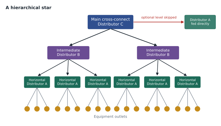
The topology at the heart of every one of these standards is a hierarchical star. Cables radiate from a central point to secondary points, and from each secondary point to the outlets it serves. There are no rings, no daisy chains and no cables that run from one outlet to the next. Each link has two ends, and every path between two points in the building passes through a known sequence of distributors.
TIA describes the points in the star with generic names. Distributor C is the top of the hierarchy, the main cross-connect, usually in the equipment room or main telecommunications room. Distributor B is an optional middle level, the intermediate cross-connect, used in large or multi-building sites. Distributor A is the horizontal cross-connect in the telecommunications room or enclosure on each floor or zone. The equipment outlet, often called the telecommunications outlet, is where the end device plugs in. ISO/IEC 11801 uses parallel names: campus distributor, building distributor, floor distributor and telecommunications outlet.
| Level | TIA name | Common name | ISO/IEC 11801 name | Typical location |
|---|---|---|---|---|
| Top | Distributor C | Main cross-connect (MC) | Campus distributor (CD) | Equipment room or main room |
| Middle (optional) | Distributor B | Intermediate cross-connect (IC) | Building distributor (BD) | Building entrance or equipment room in each building |
| Floor or zone | Distributor A | Horizontal cross-connect (HC) | Floor distributor (FD) | Telecommunications room or enclosure |
| End | Equipment outlet (EO) | Telecommunications outlet | Telecommunications outlet (TO) | Work area, ceiling or device location |
The cabling subsystems
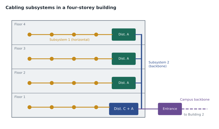
The cables that join the points are grouped into subsystems. Cabling Subsystem 1 runs from the equipment outlet to Distributor A; in older and everyday language this is horizontal cabling. Cabling Subsystem 2 runs from Distributor A to Distributor B, or straight to Distributor C if there is no B. Cabling Subsystem 3 runs from Distributor B to Distributor C. Subsystems 2 and 3 together are what designers call backbone cabling. Inside one building, backbone usually rises through a riser shaft or sleeves between floors; between buildings it becomes campus backbone, often in outside plant pathways.
The standard limits the depth of the hierarchy. There may be no more than two levels of cross-connect in the backbone: from Distributor C to Distributor B, and from Distributor B to Distributor A. A third level would add connections, loss and administrative confusion, and it is not allowed. Horizontal cabling, in turn, allows at most one optional consolidation point between the horizontal cross-connect and the outlet, a topic for lesson 4. These limits keep the number of connections in any channel small and predictable, which is what lets the standards guarantee performance.
The standard also forbids certain shortcuts. Bridged taps, the parallel branches common in old telephone wiring, are not allowed in the cabling plant, and splices are not allowed in horizontal twisted-pair cabling. Application-specific devices such as baluns, splitters and impedance-matching adapters must not be built into the cabling; if a system needs them, they are placed outside the cabling, as part of the equipment. The cabling itself stays generic.
Why a star, not a bus or a ring
Daniel asks why the standards insist on a star when some networks are logically rings or buses. Roz's answer is that the physical topology and the logical topology are different things. A star can carry a logical ring or bus by patching at the cross-connects, but a physical ring or bus cannot easily become a star. The star also isolates faults: a damaged cable affects one outlet, not every outlet downstream of it. And it centralizes administration. Every move, add or change happens with a patch cord at a cross-connect, not with a ladder and new cable.
Some modern systems challenge the star. Building automation devices, lighting controls and sensors are sometimes daisy-chained by their manufacturers, and industrial networks often use rings for redundancy. Standards such as ANSI/TIA-862 and the ISO/IEC 11801 part for distributed building services bring these devices into the structured system by giving them service outlets connected in a star from the telecommunications room. Where a device really needs a ring, the ring is built logically by patching, while the cabling remains a star. Lesson 11 and RCDD-114 return to these coverage-area designs.
Elements of the infrastructure
A cabling design never exists on its own. It depends on the spaces and pathways covered in RCDD-111: the entrance facility where service providers and campus cable enter the building, the equipment room that houses Distributor C and major equipment, the telecommunications rooms or enclosures that house Distributor A, and the backbone and horizontal pathways that join them. A designer working on the cabling must check each of these: that the room is large enough for the racks and cable management the design needs, that the pathway can hold the cable count, and that the bend radius and fill rules can be met. Cabling designers and space designers must talk constantly, and on Harborview Daniel will be both.
Grouping by subsystem also helps with project scope. Many contracts split horizontal and backbone work, and service providers often deliver their own cable only as far as the entrance facility. A clear subsystem plan tells everyone where their responsibility begins and ends, and it tells the commissioning team which test applies to which link. Horizontal links are certified as permanent links, backbone fiber is tested for loss and sometimes with an optical time domain reflectometer, and campus cables may need their own outside plant tests.
Worked problem
Mapping Harborview to the hierarchy
The Harborview building has four floors and an equipment room on the ground floor. The older building across the campus has its own telecommunications room that will be served from the new equipment room. Identify the distributors and subsystems.
Show solution
- The equipment room on the ground floor holds Distributor C, the main cross-connect for the whole campus.
- Each floor of the new building gets a telecommunications room holding Distributor A; the ground floor's Distributor A can share the equipment room.
- The older building is served by a campus cable. Because it is small and has only one room, its room can be treated as Distributor A fed directly from Distributor C, or as Distributor B if it will later feed several rooms of its own.
- Cables from each floor's Distributor A to the outlets on that floor are Cabling Subsystem 1, the horizontal cabling.
- Cables from each Distributor A to Distributor C are Cabling Subsystem 2; if the older building is designed as Distributor B, the cable from it to Distributor C is Subsystem 3.
Answer: The design is a hierarchical star with Distributor C in the equipment room and Distributor A on each floor. The older building is either another Distributor A or a Distributor B, and that choice should be made on expected growth.
Worked problem
Counting cross-connect levels
A contractor proposes a cabling plan for a large hospital campus: a main cross-connect in the data center, a building cross-connect in each wing, a floor cross-connect in each wing's main room, and then a second cross-connect in each department's small room before the horizontal cabling begins. Does the plan meet the topology rules?
Show solution
- Count the backbone cross-connect levels between the top and the horizontal cabling.
- Main cross-connect to building cross-connect is one level, building to floor cross-connect is a second, and floor to department room is a third.
- The standards allow at most two levels of backbone cross-connect below the main cross-connect.
- The fix is to make the department rooms the horizontal cross-connects, fed directly from the building cross-connect, or to serve departments directly from the floor room if distances allow.
Answer: The plan has three levels of backbone cross-connect and fails the rule. Removing one level restores the hierarchical star.
What the designer owns
An RCDD's job on a project like Harborview is to turn the owner's needs into a cabling design that meets the standards, the codes and the budget. In this course that means deciding the topology, the number and location of outlets, the media, the length limits, the hardware, the cable management, the power that the cabling will carry and the capacity for growth. Each lesson takes one of those decisions in turn, and lesson 12 puts them together into a complete design for one floor and the backbone that serves it.
Roz gives Daniel his first assignment: redraw her old riser diagram as a hierarchical star using today's names. He finds that her 2004 design already had the shape, even if the labels were different. The principles have lasted for more than three decades because they work. What has changed is the media, the bandwidth and the number of devices, and that is where most of this course will spend its time.
Common mistakes
MistakeTreating the intermediate cross-connect as required.
InsteadDistributor B is optional; small sites run backbone straight from Distributor A to Distributor C.
MistakeAdding a third level of backbone cross-connect for convenience.
InsteadThe hierarchy allows at most two backbone cross-connect levels.
MistakeDaisy-chaining outlets to save cable.
InsteadEvery outlet is a separate home run in a star from its horizontal cross-connect.
MistakeBuilding baluns or splitters into the cabling.
InsteadApplication-specific devices sit outside the generic cabling, with the equipment.
MistakeConfusing logical and physical topology.
InsteadA physical star can carry logical rings or buses by patching at cross-connects.
Summary and key terms
- Structured cabling is a generic, vendor-neutral system designed to carry many applications over a 15- to 20-year life.
- The ANSI/TIA-568 series and ISO/IEC 11801 define the topology; 569, 606, 607 and 758 cover spaces, labeling, bonding and outside plant.
- The topology is a hierarchical star: Distributor C, an optional Distributor B, Distributor A on each floor, and equipment outlets.
- Cabling Subsystem 1 is horizontal; Subsystems 2 and 3 are backbone.
- No more than two levels of backbone cross-connect are allowed, and horizontal cabling may have one consolidation point.
- Bridged taps, horizontal splices in twisted-pair and built-in application devices are not allowed.
- A physical star can carry any logical topology by patching.
- Structured cabling
- A generic cabling system with a standard topology, able to carry many applications.
- Hierarchical star
- A topology where cables radiate from a central point to secondary points and then to outlets.
- Distributor C
- The main cross-connect at the top of the hierarchy.
- Distributor B
- The optional intermediate cross-connect.
- Distributor A
- The horizontal cross-connect serving a floor or zone.
- Equipment outlet
- The outlet where an end device connects to the cabling.
- Cabling Subsystem 1
- Horizontal cabling, from the equipment outlet to Distributor A.
- Backbone cabling
- Cabling Subsystems 2 and 3, joining distributors.
Practice problems
Work each problem on paper first, then reveal the answer to check.
What is the main reason structured cabling is generic?
Show answer
So that it can carry many applications over a life longer than the equipment connected to it.
Name the TIA distributors from the top of the hierarchy down.
Show answer
Distributor C, Distributor B (optional) and Distributor A, then the equipment outlet.
What is the ISO/IEC 11801 name for a horizontal cross-connect?
Show answer
Floor distributor.
Which cabling subsystem is horizontal cabling?
Show answer
Cabling Subsystem 1.
How many levels of backbone cross-connect are allowed?
Show answer
Two at most.
Where are baluns and splitters placed?
Show answer
Outside the cabling, as part of the equipment.
Why is a star easier to administer than a bus?
Show answer
Moves and changes are made by patching at a cross-connect, and a fault affects only one link.
Lesson quiz · 5 questions
Score 60% or more to complete this lesson.
Create a free account to save your progress, take quizzes and earn a certificate.