
RAC-420 · Lesson 8 of 12 · 17 min
Operation and maintenance: oil draining, charging and pump-down
In June, Grand Valley's operators asked Ingrid's group to help with three jobs in one week: the monthly oil draining from the intercooler and recirculator, the replacement of a leaking evaporator valve station in freezer 4, and a question about the charge. The high-pressure receiver's level had been falling slowly for two months, and the chief operator wanted to add ammonia before the summer. Ingrid said no to the last request before she had even looked at the trend. "We find out where it went first," she said. "Adding ammonia to a plant that's losing it just feeds the leak." This lesson covers the routine operation and maintenance tasks that open, drain, charge or empty parts of an ammonia system, each of which needs a written procedure because each is a moment when ammonia and people are close together.
Operator rounds and logs
Industrial plants run on operator rounds. At set intervals, often every few hours, operators walk the plant and record pressures, temperatures, levels, compressor slide valve positions, amperages, oil pressures and temperatures, and pump differential pressures, and they look, listen and check their personal monitors for leaks. Modern plants also log data automatically, but the rounds remain important, because operators notice frost where there should not be any, a new noise, a weeping valve or a trend the controls do not flag. As RAC-410 showed for chillers, logs are only useful if someone compares them with normal values and acts on changes. At Grand Valley, the chief operator reviewed the logs every morning and kept a board of open issues.
Draining oil safely
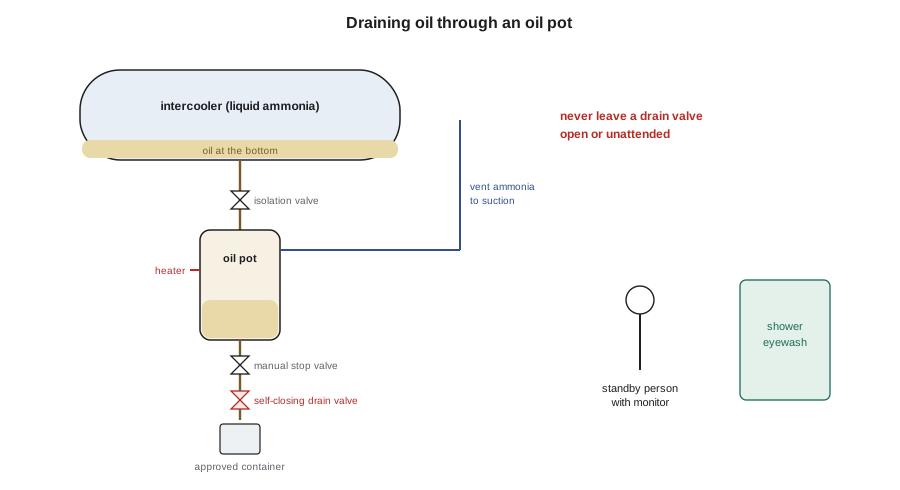
Lesson 4 explained why oil collects at low points in an ammonia plant and must be drained. Oil draining is one of the most hazardous routine tasks in ammonia refrigeration, and it has injured many workers, because it involves opening a valve that has liquid ammonia behind it, at a vessel that may hold tons of it. The oil contains dissolved and entrained ammonia, which boils off as the oil reaches atmospheric pressure. For those reasons, IIAR 7 and good practice call for a written procedure and particular equipment:
- Oil is drained from a vessel into a separate oil pot or drain vessel, which is isolated, warmed if needed and allowed to boil off its ammonia back to the suction, so that the oil leaving the pot contains as little ammonia as possible.
- The final drain valve to atmosphere is a spring-loaded, self-closing valve, sometimes called a dead-man valve, that closes automatically if it is released. It is used together with a manual stop valve upstream, so that two valves stand between the ammonia and the person.
- The drain valve is never left open or unattended, even for a moment. It is never wired, wedged or tied open.
- The person draining wears the protective equipment the procedure requires, typically a full-face respirator, chemical goggles under it or a face shield, chemical-resistant gloves and clothing, and a second person stands by with a monitor and access to the shower and eyewash.
- Oil is drained into an approved container and handled as a waste that may contain ammonia, in a ventilated area.
Draining oil directly from a cold vessel full of liquid, without an oil pot, is especially dangerous, because cold oil flows slowly and a worker may be tempted to open the valve further, and when the oil is gone, liquid ammonia follows instantly. At Grand Valley, the intercooler and recirculator both had oil pots, and the drain procedure was posted at each one with the valve numbers. Theo watched the chief operator do the first drain and did the second under supervision. The intercooler gave up nearly 3 gal of oil, more than usual, which was the oil that had passed HS-3's damaged separator in lesson 4.
Isolating, pumping out and opening equipment
To repair or replace a component, such as the evaporator valve station in freezer 4, the component must be isolated from the rest of the system, emptied of ammonia and made safe before it is opened. A typical procedure, in outline, is:
- Plan the isolation from the drawings, listing every valve that must be closed and every point where pressure will be checked, and have the plan reviewed by a second person.
- Pump out the liquid first: close the liquid feed and let the coil boil off its liquid to the suction, or transfer liquid to another vessel, so that no liquid is trapped when the isolation valves are closed.
- Close and lock the isolation valves, and lock out the electrical supply to the solenoids, fans and controls involved, under the plant's lockout procedure.
- Reduce the pressure in the isolated section to near atmospheric by venting its vapor to the compressor suction, then confirm with a gauge that it stays there.
- Remove any remaining ammonia by evacuating the section or purging it into water or a treatment system, as the procedure allows, and confirm with a monitor at the opening point.
- Only then open the flanges or cut the pipe, wearing the protection the procedure requires, with a second person standing by.
The final step before opening, confirming zero pressure and a safe concentration, is the one that prevents the most injuries, because valves leak through, gauges stick, and liquid trapped behind a closed valve can vaporize. Ingrid insisted on two independent indications: a gauge reading and a monitor reading at a cracked bleed valve, before any flange bolt was loosened. When the work is finished, the section is pressure tested with nitrogen, evacuated and then reconnected to the system, slowly, under the procedure, and the lockouts are removed only by the people who applied them.
Charging and the charge record
Ammonia is delivered by bulk trucks or in cylinders, and charging a large plant is a planned operation, not a routine one. The plant's procedure covers checking the delivery documents and the product grade, which should be refrigeration grade with very low water content; connecting the delivery hose to the charging connection with the right fittings; protective equipment and a standby person; transferring liquid into the receiver or the low side; weighing or metering the amount; and recording it. Ammonia should never be added to a plant to compensate for a loss that has not been explained.
The receiver's level is the plant's main indicator of its charge. In a plant at a steady state, with the same loads, the same defrosts and the same vessel levels, the receiver level should be steady from one month to the next. A falling level, at the same plant state, means ammonia is leaving the system, or moving into some part of it where it should not be, such as an evaporator that is filling with oil or liquid that is not draining. The script converts Grand Valley's receiver level readings to an estimate of the liquid in the receiver.
# Charge reconciliation from receiver level (horizontal cylinder, illustrative)
import math
D, L = 4.0, 20.0                      # ft, receiver inside diameter and length
rho = 37.2                            # lb/ft3, liquid ammonia at about 86 F (approximate)
def liquid_lb(level_pct):
    h = D * level_pct / 100
    r = D / 2
    area = r * r * math.acos((r - h) / r) - (r - h) * math.sqrt(2 * r * h - h * h)
    return area * L * rho
readings = [("Sept 1", 38.0), ("Oct 1", 36.5), ("Nov 1", 33.0)]   # same plant state each time
prev = None
for day, lvl in readings:
    lb = liquid_lb(lvl)
    change = "" if prev is None else f"  change {lb - prev:+.0f} lb"
    print(f"{day:7s} level {lvl:4.1f} % -> {lb:6,.0f} lb in the receiver{change}")
    prev = lb
loss = liquid_lb(readings[0][1]) - liquid_lb(readings[-1][1])
print(f"two-month apparent loss about {loss:.0f} lb: find it before adding any ammonia")Sept 1 level 38.0 % -> 3,260 lb in the receiver Oct 1 level 36.5 % -> 3,087 lb in the receiver change -173 lb Nov 1 level 33.0 % -> 2,691 lb in the receiver change -397 lb two-month apparent loss about 569 lb: find it before adding any ammonia
Over two months, at the same plant state each time, the receiver level had fallen from 38 % to 33 %, about 570 lb of ammonia. That is too much to be measurement error and too little to have been noticed as a release, which is typical of a slow leak somewhere in a large plant. The search began with the plant's leak detection: a walk of every room and the roof with monitors, looking for frost, oil stains and the white fumes ammonia forms with moist air, and checking the evaporative condenser's water, because a leaking condenser tube puts ammonia into the spray water, where it raises the pH and is lost in the blowdown. The condenser water's pH had risen from its usual value to above 9, and a test kit showed ammonia in it. A section of the condenser coil had a pinhole leak, found the next week with the section isolated and pressure tested. It was repaired before any ammonia was added.
Water and air in the system
Two contaminants matter in ammonia systems. Water enters through leaks on the low side when it runs below atmospheric pressure, through poor evacuation after maintenance and through wet ammonia deliveries. Because ammonia absorbs water, water does not freeze in expansion valves as it does in HFC systems; instead it accumulates in the low side, raises the boiling temperature at a given pressure and reduces capacity and efficiency. Plants test for water by sampling liquid from the low side and evaporating the ammonia to measure the residue, and remove it with ammonia regenerators or by draining contaminated liquid. Air and other non-condensable gases collect in the condenser and receiver and raise the condensing pressure. Plants remove them with automatic purgers, which vent the non-condensables through water or to a safe point after condensing out the ammonia. A rising head pressure with a normal condenser and load suggests non-condensables, and the purger should be checked.
Shutdowns and decommissioning
For a major shutdown, such as a vessel inspection, the plant may need to pump the ammonia from one part of the system into others, usually into the high-pressure receiver, which is sized to hold most of the charge. Pump-down must be planned so that no vessel is overfilled. Liquid expands as it warms, and a vessel filled to more than about 90 % of its volume with cold liquid can become liquid-full and develop hydrostatic pressure as it warms, as lesson 5 explained. When a system or a part of one is taken out of service permanently, IIAR 8 sets out the decommissioning steps, including removing the ammonia, which may be sold back to a supplier, recycled or neutralized, and making the equipment safe and recording what was done.
| Task | Main hazard | Key controls |
|---|---|---|
| Oil draining | Liquid ammonia following the oil | Oil pot, two valves including a self-closing one, never unattended, PPE, standby person |
| Opening equipment | Trapped liquid or vapor behind closed valves | Isolation plan, pump-out, lockout, zero-pressure and monitor checks, second person |
| Charging | Hose or fitting failure; overfilling | Procedure, correct fittings, standby person, metering, records |
| Pump-down | Overfilled vessels | Plan, level limits near 90 %, monitoring |
| Leak search | Unknown concentrations | Personal monitors, respirators by reading, never alone |
Common mistakes
MistakeLeaving an oil drain valve open while fetching another container.
InsteadNever leave a drain valve open or unattended; use a self-closing valve with a manual stop upstream.
MistakeDraining oil directly from a cold vessel.
InsteadDrain to an oil pot, boil off the ammonia, then drain the pot.
MistakeTrusting one closed valve and one gauge before opening a flange.
InsteadConfirm zero pressure and a safe concentration with independent checks.
MistakeTopping up a falling receiver level before summer.
InsteadFind and fix the loss first; check the condenser water, vessels and evaporators.
MistakeFilling a vessel nearly full of cold liquid during pump-down.
InsteadKeep vessel levels below the plan's limit, around 90 %, to allow for expansion.
Summary and key terms
- Operator rounds and logs, compared with normal values, are the first line of detection.
- Oil draining is among the most hazardous routine tasks; it uses oil pots, two valves including a self-closing one, PPE and a standby person, and is never left unattended.
- Equipment is isolated by plan, pumped out, locked out, checked for zero pressure and safe concentration, and then opened.
- Charging is planned and recorded; a falling receiver level at the same plant state means ammonia is going somewhere and must be explained first.
- Water lowers capacity and is removed by regeneration; non-condensables raise head pressure and are removed by purgers.
- Pump-downs avoid overfilled vessels; decommissioning follows IIAR 8.
- Oil pot
- A small vessel into which oil is drained from a larger vessel so that its ammonia can boil off before the oil is removed.
- Self-closing drain valve
- A spring-loaded valve that closes automatically when released.
- Pump-out
- Removing liquid and vapor from a section of a system before it is isolated and opened.
- Purger
- A device that removes air and other non-condensable gases from the condenser and receiver.
- Ammonia regenerator
- A device that removes water from ammonia by distilling the ammonia off.
- Receiver level
- The liquid level in the high-pressure receiver, the main indicator of a plant's charge.
Practice problems
Work each problem on paper first, then reveal the answer to check.
A receiver level falls by 4 % over a month at the same plant state, about 450 lb. What should be done before adding ammonia?
Show answer
Find the loss: walk the plant with monitors, check the condenser water, vessels and evaporators.
Why must the oil drain valve be self-closing?
Show answer
So that it closes automatically if the person releases it or is overcome.
What two checks should be made before opening a flange on an isolated section?
Show answer
Zero pressure on a gauge, and a safe reading on a monitor at a bleed point.
What symptom suggests non-condensables in an ammonia plant?
Show answer
A rising head pressure with a normal condenser and load.
Lesson quiz · 5 questions
Score 60% or more to complete this lesson.
Create a free account to save your progress, take quizzes and earn a certificate.