
RAC-420 · Lesson 5 of 12 · 18 min
Valves, piping and pressure relief
In March, Hannah's mechanical integrity schedule showed that the relief valves on Grand Valley's high-pressure receiver were past their five-year replacement date. Ingrid planned the job with Luis and his chief operator. The receiver had two relief valves on a three-way changeover valve, so one could be isolated and replaced while the other protected the vessel. Theo spent an evening with the plant's relief system drawing, tracing every relief line from the vessels to the common header and up through the roof to the discharge point. "Most of the time these valves do nothing," Ingrid said. "They're there for the one day everything else has gone wrong." This lesson covers the valves and piping of ammonia systems and the relief systems that protect them.
Piping and materials
Ammonia piping is carbon steel, usually seamless schedule 40 or 80 pipe for smaller sizes and schedule 40 for larger, or stainless steel, joined by welding, with flanged or threaded connections only where codes allow. The piping is designed and installed to ASME B31.5, Refrigeration Piping and Heat Transfer Components, and IIAR 2 and IIAR 4, with welds made by qualified welders to qualified procedures. Welded joints are examined, the completed system is pressure tested, and the piping is labeled. Cold lines are insulated with a continuous vapor retarder on the outside, because any gap lets moist air reach the cold steel, where it condenses, freezes and corrodes.
Piping is supported and anchored to carry its weight, the weight of liquid, thermal movement and the forces of hydraulic shock or a relief discharge. Lines are sloped to drain liquid where they should and to avoid traps where liquid could collect and later be pushed through as a slug. Physical protection matters as well: in warehouses and food plants, piping near forklift traffic, dock doors and roof equipment needs guards, because an impact can break a small line or a valve.
Valves
An ammonia plant has hundreds of valves, and a technician must recognize each type and what it does.
- Isolation valves, globe, angle or ball valves, stop flow so that equipment can be worked on. Stop valves on ammonia systems often have seal caps, which are kept on except when the valve is operated, and some have packing that must be checked for leaks.
- Check valves allow flow in one direction only, for example in compressor discharges and pump outlets.
- Solenoid valves open and close on control signals, for liquid feed, suction and hot gas lines.
- Pressure regulators hold an upstream or downstream pressure, for example to control evaporator pressure or drain defrost condensate.
- Motorized and electronic expansion valves meter liquid to evaporators and vessels.
- Hand expansion valves and metering valves set a fixed flow.
- Relief valves open at a set pressure to protect equipment from overpressure.
Valve groups, or valve stations, are assembled at each evaporator so that it can be fed, defrosted and isolated. Isolation valves must be able to close tightly when a component is being opened for work, and where an isolation must be positive, plants use two closed valves with a bleed point between them, or blind flanges, according to IIAR 6 and their own procedures. Valves are tagged with numbers that match the drawings and isolation plans, and their normal positions, open or closed, are listed so that operators can check them on their rounds.
Trapped liquid and hydrostatic pressure
One of the most important facts about liquid refrigerant is what happens when it is trapped. If a length of pipe completely full of liquid ammonia is closed at both ends, for example by two isolation valves or a solenoid and a check valve, and then warms up, the liquid tries to expand but cannot. Liquids are almost incompressible, so the pressure rises enormously. The script estimates the rise for liquid ammonia using its approximate expansion coefficient and compressibility.
# Relief capacity by the C = f D L form, and why trapped liquid is dangerous (approximate)
f = 0.5                      # lb of air per minute per ft2 for ammonia (illustrative code factor)
vessels = {"high-pressure receiver": (4.0, 20.0), "LT recirculator": (5.0, 15.0), "intercooler": (3.3, 10.0)}
for name, (D, L) in vessels.items():
    C = f * D * L
    print(f"{name:23s} D {D} ft, L {L} ft -> relief capacity at least {C:.1f} lb of air per minute")
# liquid ammonia trapped between two closed valves, warming up
beta = 0.0024 / 1.8          # 1/F, thermal expansion of liquid ammonia near 32 to 68 F (approximate)
kappa = 1.1e-9 * 6895        # 1/psi, compressibility of liquid ammonia (approximate)
for dT in (2, 9, 18):
    dp = beta * dT / kappa   # pressure rise if the pipe could not stretch at all
    print(f"warming trapped liquid by {dT:2d} F could raise the pressure by about {dp:,.0f} psi")
print("Real pipe stretches a little, but the rise is still far beyond any piping rating.")high-pressure receiver D 4.0 ft, L 20.0 ft -> relief capacity at least 40.0 lb of air per minute LT recirculator D 5.0 ft, L 15.0 ft -> relief capacity at least 37.5 lb of air per minute intercooler D 3.3 ft, L 10.0 ft -> relief capacity at least 16.5 lb of air per minute warming trapped liquid by 2 F could raise the pressure by about 352 psi warming trapped liquid by 9 F could raise the pressure by about 1,582 psi warming trapped liquid by 18 F could raise the pressure by about 3,164 psi Real pipe stretches a little, but the rise is still far beyond any piping rating.
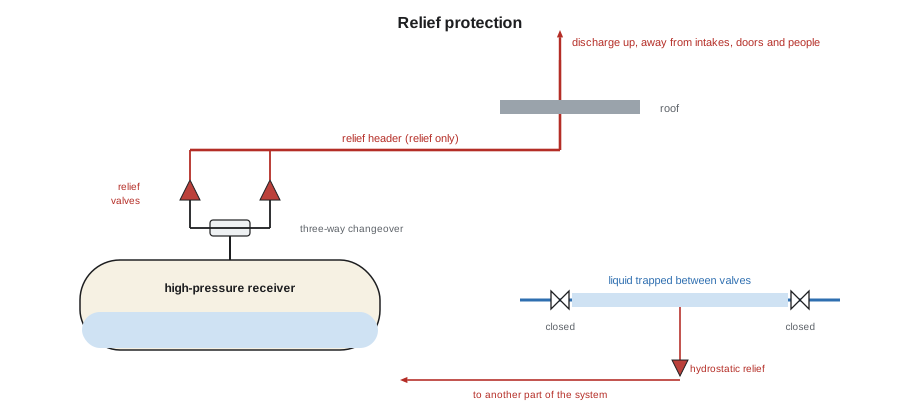
Warming trapped liquid ammonia by just 2 °F could raise the pressure by about 350 psi if the pipe could not stretch, and by 18 °F, about 3,200 psi. The pipe and valves do stretch a little, but the pressure still rises far beyond what valves, gaskets, gauges and sight glasses are rated for, and failures from trapped liquid have caused serious releases. That is why codes require relief protection for any section of liquid line that can be isolated, typically a small hydrostatic relief valve that relieves into another part of the system, and why procedures for isolating liquid lines always say how the trapped liquid will be removed or protected first. The first part of the script shows the other side of relief: the minimum discharge capacity required for a vessel exposed to fire.
Pressure relief for vessels
Every pressure vessel in a refrigeration system must be protected against overpressure. The worst case codes consider is fire: a vessel engulfed in flames heats its liquid, which boils, and the vapor must be relieved fast enough that the pressure does not exceed safe limits. The codes therefore give the minimum relief capacity in a simple form that depends on the vessel's outside dimensions and the refrigerant:
where C is the minimum required capacity of the relief device in pounds of air per minute, D and L are the vessel's outside diameter and length, and f is a factor tabulated for each refrigerant. For ammonia, with its high latent heat, the factor is about half that for most fluorocarbons. The script used an illustrative factor; the value in the code in force must always be used. The relief valve chosen must have a certified capacity at least equal to C, at its set pressure, which is no higher than the vessel's design pressure.
Relief valves must also be arranged so that the vessel is never left unprotected. A three-way changeover valve with two relief valves lets one be removed while the other stays in service, and it cannot isolate both at once. Stop valves are not allowed between a vessel and its only relief valve. Relief valves are not repaired in the field; IIAR 6 calls for them to be replaced on a schedule, commonly every five years, or sooner if they have discharged or show corrosion, and the replacement and its date are recorded.
Where relief goes
A relief discharge from an ammonia vessel releases ammonia, possibly a large quantity, so where it goes matters as much as how big the valve is. Codes require the discharge pipe to be sized so that the back pressure does not prevent the valves from opening fully, and to terminate outdoors at a safe place: well above the roof, pointing upward, away from doors, windows, air intakes and places people could be, and protected from rain and blockage. Some installations route relief discharges to a treatment system such as a scrubber or diffusion tank, or to a flare, where local rules or the site's risk require it. IIAR 2 and the mechanical code set out the discharge requirements for ammonia relief in the United States.
Relief headers collect discharges from several valves into one line, and the header must be sized for the possible flows. Ingrid had Theo check that no one had connected any other vents to Grand Valley's header since it was installed, because a header that receives vents from other equipment can be pressurized enough to stop a relief valve from lifting. He also checked that the discharge outlet's rain cap was free and that a recent rooftop unit had not been installed near it. It had not, but the new office's air intake was closer than the original drawings showed. Hannah raised a management of change review, as lesson 7 describes, to decide whether the outlet should be extended.
Pressure, temperature and design limits
Each part of an ammonia system has a design pressure, set by the code according to the part's location in the system and the highest temperature it could reach. The high side is designed for the pressure of ammonia at a high condensing temperature, and the low side for the pressure the low side could reach when the plant is shut down in summer and everything warms to the ambient temperature. Equipment ratings, test pressures and relief settings follow from those design pressures. Technicians must never raise a relief setting, block a relief valve or modify a vessel's relief arrangement; those are changes that need engineering and management of change.
Pressure tests of new and modified piping are done with dry nitrogen or air at the pressure the code specifies, never with water in ammonia systems because of the moisture it leaves, and never with oxygen. The test is held for the specified time with all joints checked, and the results are recorded. After a test, the system is evacuated to remove moisture and air before ammonia is admitted, as lesson 8 describes.
The relief valve job
The receiver's relief valve replacement followed a written procedure. The new valves, ordered to the specification on the plant's records, with the correct set pressure, capacity and connection, were checked against the nameplate before the job. With the changeover valve set to the right-hand valve, Ingrid and Theo confirmed with a gauge that the left-hand valve's inlet was isolated and at no pressure, and then removed and replaced it, with new gaskets and bolting, while a second person stood by with the monitor. The changeover was then moved to the new valve, and the right-hand one replaced the same way. The changeover was left in its normal position and sealed, and the records were updated with the valves' serial numbers, set pressure and date. The old valves were tagged and kept for the manufacturer's inspection, because one had a little rust inside its discharge, which suggested moisture getting down the relief line.
| Hazard | Protection |
|---|---|
| Fire or overheating of a vessel | Relief valves sized to C = f D L, discharging to a safe place |
| Trapped liquid warming in an isolated line | Hydrostatic relief; procedures to remove liquid before isolation |
| Removal of a relief valve for service | Dual relief valves on a three-way changeover |
| Back pressure in a relief header | Header sized for all valves; no other vents connected |
| Corrosion or sticking of relief valves | Scheduled replacement, typically every five years, and inspection of discharge lines |
Common mistakes
MistakeClosing two valves on a full liquid line and leaving it.
InsteadRemove or protect the trapped liquid first; hydrostatic pressure can burst the line.
MistakeFitting a stop valve between a vessel and its only relief valve.
InsteadUse a three-way changeover with two relief valves.
MistakeConnecting a drain or vent to the relief header for convenience.
InsteadKeep the header for relief only; extra flows add back pressure.
MistakeRepairing or adjusting a relief valve in the field.
InsteadReplace relief valves on schedule with certified, correctly set valves.
MistakePressure testing ammonia piping with water.
InsteadUse dry nitrogen or air at the code pressure, then evacuate.
Summary and key terms
- Ammonia piping is welded steel built to the refrigeration piping code, insulated with a continuous vapor retarder on cold lines.
- Isolation, check, solenoid, regulating, expansion and relief valves each have specific roles; valves are numbered and their normal positions listed.
- Trapped liquid that warms can reach enormous pressures, so isolable liquid lines need hydrostatic relief and careful procedures.
- Vessel relief capacity is set by C = f D L for fire exposure; relief valves are certified, set no higher than design pressure and replaced on schedule.
- Relief discharges go outdoors to a safe point, through headers sized for the flow, sometimes to treatment.
- Changing relief settings or arrangements requires engineering and management of change.
- Hydrostatic expansion
- The pressure rise in liquid trapped in a closed space as it warms.
- Hydrostatic relief valve
- A small relief valve that protects an isolable section of liquid line.
- Three-way changeover valve
- A valve that connects one of two relief valves to a vessel, so one can be removed safely.
- Relief header
- A pipe that collects discharges from several relief valves to a common outlet.
- Design pressure
- The maximum pressure a component is designed to withstand, set by code.
- Vapor retarder
- A continuous layer on the outside of insulation that stops moist air from reaching cold pipe.
Practice problems
Work each problem on paper first, then reveal the answer to check.
A vessel is 3.5 ft in diameter and 12 ft long. With f = 0.5, what minimum relief capacity is required?
Show answer
0.5 × 3.5 × 12 = 21 lb of air per minute.
Why must liquid be removed from a line before both ends are closed?
Show answer
Warming trapped liquid can raise the pressure enormously and burst the line.
Why are relief valves on receivers installed in pairs with a changeover valve?
Show answer
So one can be replaced while the other protects the vessel.
Give three requirements for the location of a relief discharge.
Show answer
Outdoors, well above the roof and pointing up, away from doors, windows, intakes and people.
Lesson quiz · 5 questions
Score 60% or more to complete this lesson.
Create a free account to save your progress, take quizzes and earn a certificate.