
RAC-420 · Lesson 3 of 12 · 17 min
Industrial ammonia system types
Ingrid's way of teaching a plant was to walk the refrigerant. On Theo's second week at Grand Valley she started at the evaporative condenser on the roof and followed the liquid down to the high-pressure receiver, through the intercooler, into the recirculator, out through the pumps to the freezer evaporators, and back as a mix of liquid and vapor, then up through the booster compressors, the intercooler and the high-stage compressors to the condenser again. It took most of a morning. "Every plant is different," she said, "but they're all built from a few ideas. Once you see the ideas, you can read any plant." This lesson describes those ideas: how ammonia is fed to evaporators, how two-stage systems work, and the newer low-charge designs.
Single-stage systems
The simplest industrial system has one stage of compression: compressors draw vapor from the evaporators or from a suction accumulator, discharge it to a condenser, and the liquid drains to a receiver and returns to the evaporators through expansion valves. Single-stage ammonia systems are common for coolers, chillers, rinks and process cooling where the evaporating temperature is not very low. As the evaporating temperature falls, however, the pressure ratio rises, and a single compressor becomes inefficient and runs very hot, because ammonia has a high ratio of specific heats and its discharge temperature climbs quickly with the ratio.
Feeding the evaporators
Industrial evaporators can be fed in three main ways, and the choice shapes the whole plant.
- Direct expansion. As in commercial systems, an expansion valve meters just enough liquid to evaporate completely in the coil, with superheat at the outlet. Ammonia's high latent heat means very small flows, which made direct expansion difficult with older valves; modern electronic valves have made ammonia direct expansion practical in many low-charge systems.
- Flooded. The evaporator is connected to a surge drum or accumulator above it, and liquid flows into the coil by gravity, while the vapor formed returns to the drum. The coil is always full of boiling liquid, which gives excellent heat transfer, but the charge is large. The arena's brine chiller is a flooded shell-and-tube evaporator.
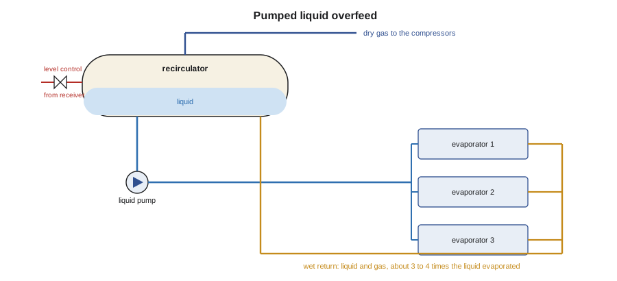
- Liquid overfeed, or recirculated. A pump or gas pressure pushes several times more liquid through the evaporators than they can evaporate. The excess liquid returns with the vapor to a vessel called a recirculator or pumper drum, where they separate: the compressors draw vapor from the top, and the pumps take liquid from the bottom. The ratio of liquid pumped to liquid evaporated is the circulation rate, typically about 3:1 to 4:1. Overfed coils are fully wetted, have no superheat zone and transfer heat well, and the recirculator protects the compressors from liquid. Most large freezer plants, including Grand Valley's, are recirculated.
Recirculated systems need a careful arrangement. The pumps must have enough liquid height above their inlets, called net positive suction head, or the liquid flashes in the pump and it loses prime; this is why recirculators are tall vessels mounted high, and why pumps are often below the floor in a pit. The vessel must be large enough to hold the liquid that drains back from the evaporators when they stop or defrost, without flooding the compressors' suction. Level controls feed liquid from the high-pressure receiver to keep a steady level, and high-level switches stop the compressors before liquid can reach them.
Two-stage systems
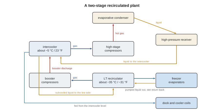
For freezers and blast freezers, plants use two stages of compression. Booster, or low-stage, compressors take vapor from the low-temperature recirculator and compress it to an intermediate pressure. High-stage compressors then take vapor at the intermediate pressure and compress it to the condensing pressure. Between them sits an intercooler, a vessel at the intermediate pressure in which the hot booster discharge is cooled, usually by bubbling it through liquid ammonia, and from which the high stage draws its suction. The intercooler also subcools the liquid going to the low-temperature side, through a coil or by flashing, which reduces the flash gas the booster must handle. Higher-temperature loads, such as docks and coolers, often run at the intermediate pressure, so the intercooler doubles as their recirculator or surge drum.
Splitting the compression has two big advantages: each compressor works across a smaller pressure ratio, so it is more efficient and runs cooler, and the high-stage compressors handle vapor that has been cooled, so they need less work. A common first estimate of the best intermediate pressure is the geometric mean of the evaporating and condensing pressures, which gives equal pressure ratios in the two stages; designers then adjust it for the loads at the intermediate level and the compressors available. The script works through Grand Valley's numbers: the intermediate pressure, the stage ratios, the ideal discharge temperatures and the liquid the pumps must circulate.
# Two-stage ammonia: intermediate pressure, stage ratios, discharge temperature and liquid recirculation
import math
psia = {-31: 13.5, 23: 51.4, 95: 195.8}      # approximate saturation pressures, psia
pe, pc = psia[-31], psia[95]
pi = math.sqrt(pe * pc)                      # geometric mean: equal pressure ratios
print(f"single stage: ratio {pc / pe:.1f}")
print(f"two stage: intermediate {pi:.1f} psia = {pi - 14.7:.1f} psig (about 23 F), ratios {pi / pe:.2f} and {pc / pi:.2f}")
k = 1.31                                     # ratio of specific heats for ammonia vapor
T1 = -22 + 459.67                            # suction gas at -22 F after superheat, in Rankine
for name, r in [("single stage", pc / pe), ("each stage of two", pi / pe)]:
    T2 = T1 * r ** ((k - 1) / k)
    print(f"{name:18s} ideal discharge about {T2 - 459.67:4.0f} F (real machines run hotter without cooling)")
# liquid overfeed to the freezer evaporators
load = 400 * 12000.0                         # Btu/h at -31 F
hfg = 585.0                                  # Btu/lb, latent heat at -31 F (approximate)
rho = 42.6                                   # lb/ft3, liquid at -31 F (approximate)
evap = load / hfg / 60                       # lb/min
for n in (3, 4):
    pumped = n * evap
print(f"circulation rate {n}:1 -> evaporated {evap:.1f} lb/min, pumped {pumped:.0f} lb/min = {pumped / rho * 7.48:.0f} gpm")single stage: ratio 14.5 two stage: intermediate 51.4 psia = 36.7 psig (about 23 F), ratios 3.81 and 3.81 single stage ideal discharge about 364 F (real machines run hotter without cooling) each stage of two ideal discharge about 141 F (real machines run hotter without cooling) circulation rate 3:1 -> evaporated 136.8 lb/min, pumped 410 lb/min = 72 gpm circulation rate 4:1 -> evaporated 136.8 lb/min, pumped 547 lb/min = 96 gpm
A single stage from −31 °F to 95 °F condensing would work across a pressure ratio of about 14.5, with an ideal discharge temperature near 364 °F, far too hot for oil and valves. Two stages with an intermediate pressure of about 37 psig, near 23 °F saturation, split it into two ratios of about 3.8, with ideal discharge temperatures near 141 °F. And the freezer evaporators, evaporating about 137 lb/min, needed the pumps to circulate 410 to 550 lb/min, about 72 to 96 gpm of liquid. Real compressors discharge hotter than the ideal figures, which is why screw compressors inject oil and are fitted with oil coolers, as lesson 4 explains.
Defrost and the hot gas system
Freezer evaporators collect frost and must be defrosted, usually with hot gas from the high-stage discharge in industrial ammonia systems, or with water or electric heat in some plants. In a hot gas defrost, the coil's liquid supply and suction are closed, the coil is pumped out, and hot gas is admitted to warm it and melt the frost; the condensed liquid leaves through a pressure regulator or a liquid drainer to the suction or the intercooler. The sequence matters greatly for safety. Opening hot gas to a coil full of cold liquid, or suddenly opening a coil at high pressure to cold suction, can cause hydraulic shock, a violent pressure surge from vapor condensing into liquid or liquid slugs moving at high speed, which has burst valves, evaporators and pipes and caused serious releases. Modern defrost sequences use soft-start valves that raise pressure slowly, pump-out and bleed periods, and controls that will not skip steps. Lesson 5 returns to hydraulic shock.
Low-charge and packaged ammonia systems
Since the early 2000s, ammonia system design has moved strongly toward smaller charges. The approaches include:
- Packaged low-charge chillers. Factory-built ammonia chillers with plate or compact shell-and-plate evaporators and condensers hold a few kilograms of ammonia per hundred kilowatts. They cool a secondary fluid, glycol or brine, that is piped to the load, so no ammonia leaves the machine. Many are installed outdoors or in small enclosures, so there is no large machinery room in the building.
- Packaged units on the roof or beside each room. Small ammonia units, each serving one freezer or cooler with direct expansion or low-charge evaporators, replace one large central plant and its long ammonia piping.
- Ammonia and carbon dioxide cascades. Ammonia is kept in a compact machine and condenses carbon dioxide, which is pumped to the evaporators in the occupied areas. Lesson 11 describes these systems, which are common in new freezer warehouses and rinks.
- Better central plants. Even large site-built plants now use direct expansion or controlled-pressure-receiver designs and smaller vessels to cut the charge.
The charge per unit of capacity can fall by a factor of ten or more, which reduces the worst possible release, may bring a plant below the thresholds for process safety and emergency rules, and simplifies machinery room requirements. The tradeoffs include more complex controls, sometimes higher energy use from secondary loops, and the need for skilled service of compact components. For Hillcrest Arena, the comparison between a traditional flooded chiller and a packaged low-charge unit would be at the center of the capstone.
Reading the plant
By the end of his second week, Theo could stand in Grand Valley's engine room and say where the high-pressure liquid was, where the low-temperature liquid was, which lines carried hot gas, which carried a liquid and vapor mixture and which carried dry vapor. Ingrid made him prove it on the piping identification labels, which in ammonia plants show the refrigerant, the physical state, the pressure level and the flow direction, following an IIAR guideline. "If you can't read the label, you don't touch the pipe," she said. Every valve also had a number that matched the plant's piping drawings and procedures, so that an isolation plan could list exactly which valves to close and in what order.
| Feed method | How liquid reaches the coil | Charge | Typical use |
|---|---|---|---|
| Direct expansion | Expansion valve meters it; superheat at outlet | Low | Low-charge and packaged systems |
| Flooded | Gravity from a surge drum above the coil | High | Shell-and-tube chillers, older plants |
| Liquid overfeed | Pump or gas pressure, 3 to 4 times evaporation | Medium to high | Large freezer and cooler plants |
| Secondary fluid | Ammonia stays in a chiller; glycol or CO₂ goes to the load | Very low | Rinks, warehouses, food plants |
Controlled pressure receivers and other refinements
Some modern central plants use a controlled pressure receiver, a vessel held at a pressure between the condensing and evaporating pressures, from which liquid is fed to direct expansion evaporators. Because the receiver's pressure is controlled rather than set by the condenser, the liquid entering the expansion valves is nearly saturated and the valves see a steady pressure difference, which lets direct expansion work well at large capacities and keeps the charge low. Other refinements include high-pressure float valves that pass liquid to the low side as soon as it condenses, so that little ammonia is stored on the high side, and smaller, better-placed vessels. None of these changes the basic ideas in this lesson: they rearrange where the liquid sits and how it reaches the coils.
For a technician, the practical lesson is to learn each plant's arrangement from its drawings before working on it, because two plants that look alike from the engine room floor can store and move their ammonia very differently.
Common mistakes
MistakeStarting a recirculator pump with too little liquid height above it.
InsteadPumps need net positive suction head; low level makes them cavitate and lose prime.
MistakeOpening hot gas to a coil still full of cold liquid.
InsteadFollow the defrost sequence: pump out, then admit hot gas slowly through a soft-start valve.
MistakeAssuming a single-stage compressor can serve a deep freezer.
InsteadUse two stages, or the discharge temperature and inefficiency are unacceptable.
MistakeIgnoring the volume a recirculator needs for liquid that drains back.
InsteadSize and operate the vessel so drain-back cannot flood the compressor suction.
MistakeWorking on a pipe without reading its identification label.
InsteadConfirm the refrigerant, state, pressure level and direction first.
Summary and key terms
- Industrial evaporators are fed by direct expansion, flooded surge drums or liquid overfeed from a recirculator.
- Overfeed systems pump about 3 to 4 times the liquid that evaporates; the recirculator separates liquid and vapor and protects the compressors.
- Two-stage systems split the compression with an intercooler, improving efficiency and limiting discharge temperature.
- The geometric mean of evaporating and condensing pressures is a first estimate of the intermediate pressure.
- Hot gas defrost sequences must avoid hydraulic shock.
- Low-charge designs, packaged chillers and ammonia-CO₂ cascades cut the charge per unit of capacity by ten times or more.
- Recirculator
- A vessel that separates liquid and vapor returning from overfed evaporators and supplies liquid to the pumps.
- Circulation rate
- The ratio of liquid pumped to an evaporator to liquid evaporated in it.
- Intercooler
- A vessel at intermediate pressure that cools booster discharge gas and subcools liquid in a two-stage system.
- Booster compressor
- The low-stage compressor in a two-stage system.
- Flooded evaporator
- An evaporator kept full of liquid by gravity from a surge drum.
- Hydraulic shock
- A violent pressure surge caused by condensation of vapor into liquid or by fast-moving liquid slugs.
Practice problems
Work each problem on paper first, then reveal the answer to check.
A freezer load of 150 tons evaporates ammonia with a latent heat of 585 Btu/lb. At a 4:1 circulation rate, how much liquid must be pumped?
Show answer
1,800,000 ÷ 585 ÷ 60 = 51 lb/min evaporated; about 205 lb/min pumped.
Evaporating at 17 psia and condensing at 196 psia, what intermediate pressure gives equal ratios?
Show answer
√(17 × 196) = about 58 psia.
Why do two-stage systems need an intercooler?
Show answer
To cool the booster discharge, provide the high-stage suction and subcool liquid to the low side.
Name two ways the charge of an ammonia system can be reduced.
Show answer
Packaged low-charge chillers with a secondary fluid, direct expansion, ammonia-CO₂ cascades, smaller vessels.
Lesson quiz · 5 questions
Score 60% or more to complete this lesson.
Create a free account to save your progress, take quizzes and earn a certificate.