
NUC-440 · Lesson 3 of 12 · 20 min
Reactivity control devices
Dr. Teodora Vasquez, the core physicist who calculates rod worths and boron curves for TVA's pressurized water reactor fleet, takes Hana onto the reactor head area of a Westinghouse unit during a refueling outage. The control rod drive mechanisms stand in a tight array on the head, each housing the latch and coils that step a rod cluster up or down. “Each device in a reactor has a different job,” Teodora says. “Some hold the reactor at the right power, some shape the flux, some compensate for burnup and xenon, and some exist only to shut the reactor down. You choose the device by how much reactivity it has to handle, how fast, and how reliably.”
This lesson surveys the reactivity control devices of CANDU, pressurized water and boiling water reactors: absorber rods, soluble poisons, liquid zone controllers, adjusters and burnable absorbers. It explains how device worth depends on position and flux, why rods have integral S-shaped worth curves, and how designers divide the reactivity budget among devices with different speeds and duties.
The reactivity budget
A reactor must carry enough excess reactivity to compensate for the losses it will meet in operation: temperature and power defects as it heats up and raises power, the xenon and samarium equilibrium loads, burnup between refuelings, and margin to overcome xenon after a shutdown. It must also have enough negative reactivity available to shut down with margin under the worst conditions, usually assuming that the most reactive single rod fails to insert. Control devices are therefore sized against a reactivity budget that lists every demand and assigns it to a device.
A PWR is refueled in batches every 18 to 24 months, so each cycle starts with thousands of pcm of excess reactivity that must be held down by soluble boron and burnable absorbers and released as the fuel burns. A CANDU reactor, by contrast, is refueled on power, a few channels each day, so its control devices handle only small, fast adjustments, xenon transients and flux shaping.
CANDU devices
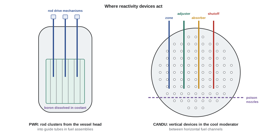
A CANDU reactor, which some students will meet in Canadian or overseas plants, places its reactivity mechanisms in the low-pressure, low-temperature moderator between the fuel channels. Its main devices are liquid zone controllers, compartments partly filled with light water, which absorbs neutrons more than heavy water; adjuster rods, normally inserted to flatten the flux and withdrawn for xenon override; mechanical control absorbers, cadmium rods driven in for fast power reductions; moderator poison, boron or gadolinium dissolved in the moderator; and two independent shutdown systems, shutoff rods and gadolinium injection.
In a CANDU reactor the zone controllers are the workhorses. The regulating system raises or lowers the water level in each compartment, moving them together to change bulk power or differentially to correct spatial tilts. Their total worth is a few milli-k, about 7 mk from empty to full, enough for routine control, with adjusters and absorbers backing them up for larger needs.
PWR devices
A pressurized water reactor controls reactivity with rod cluster control assemblies and soluble boron. Each assembly is a spider of 20 to 24 absorber rodlets, typically silver-indium-cadmium or boron carbide, that slide into guide tubes inside a fuel assembly. The assemblies are grouped into shutdown banks, which are fully withdrawn before the reactor is taken critical and serve only to shut down, and control banks, which move in an overlapped sequence to adjust power and temperature. Magnetic jack mechanisms step each rod in increments of about 1.6 centimeters (5/8 inch), at speeds up to roughly 72 steps per minute, and release it to fall by gravity when power to the coils is cut.
Soluble boron, as boric acid in the reactor coolant, handles the slow changes: burnup over the cycle, the xenon buildup after a power change, and the large shutdown margin needed for refueling. The chemical and volume control system changes boron concentration by adding concentrated boric acid (boration) or pure water (dilution) to the coolant. A boron change is uniform in space and does not distort the flux, but it is slow, minutes to hours, and an uncontrolled dilution is itself an analyzed event, because adding unborated water to a shut-down core can make it critical. Burnable absorbers such as gadolinia mixed into some fuel pellets, or integral boride coatings, hold down early-cycle excess and burn out as the cycle proceeds.
A boiling water reactor uses cruciform control blades inserted from below by hydraulic drives, together with recirculation flow, which changes the void fraction in the core. The BWRX-300 has no recirculation pumps; it relies on natural circulation and uses fine-motion control rod drives, which position the blades electrically for normal control and insert them hydraulically for a scram, together with feedwater temperature for some power adjustment.
How worth depends on position
An absorber removes reactivity roughly in proportion to the square of the flux at its location, weighted by the importance of neutrons there. A rod tip moving through a region of high flux has a large differential worth, in reactivity per unit length; moving through the low-flux ends of the core, it has little. For a cosine axial flux shape, the differential worth varies as the square of a sine and the integral worth, the total reactivity removed when the tip is at depth z, follows an S-shaped curve:
where W is the total worth and H the active height. Real curves are distorted by the rod itself, which pushes flux away from where it is inserted, by other rods, by xenon and by burnup, and they are measured during physics testing at the start of each PWR cycle by boron dilution, rod swap or dynamic rod worth measurement techniques.
# Integral and differential worth of a control rod in a cosine-flux core.
import math
H = 380.0            # active height (cm)
W_total = 9.0        # total rod worth (mk)
def integral(z):     # worth inserted when the tip is at depth z from the top
    x = z / H
    return W_total * (x - math.sin(2 * math.pi * x) / (2 * math.pi))
print(f"{'depth (cm)':>10s}{'inserted (mk)':>15s}{'differential (mk/m)':>21s}")
for z in range(0, 381, 38):
    d = (integral(min(z + 1, H)) - integral(max(z - 1, 0))) / (min(z + 1, H) - max(z - 1, 0)) * 100
    print(f"{z:10d}{integral(z):15.2f}{d:21.2f}")
# Liquid zone controllers: worth roughly linear in fill fraction over the middle of the range.
zones, worth_per_zone = 14, 0.5   # mk per compartment, full drain to full fill (illustrative)
for fill in (20, 40, 60, 80):
print(f"all zones from 50% to {fill}% full -> {zones * worth_per_zone * (fill - 50) / 100:+.2f} mk")depth (cm) inserted (mk) differential (mk/m)
0 0.00 0.00
38 0.06 0.45
76 0.44 1.64
114 1.34 3.10
152 2.76 4.28
190 4.50 4.74
228 6.24 4.28
266 7.66 3.10
304 8.56 1.64
342 8.94 0.45
380 9.00 0.00
all zones from 50% to 20% full -> -2.10 mk
all zones from 50% to 40% full -> -0.70 mk
all zones from 50% to 60% full -> +0.70 mk
all zones from 50% to 80% full -> +2.10 mk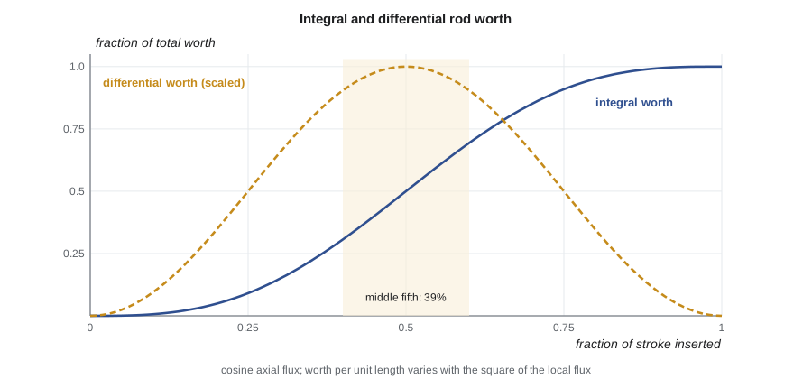
The table shows that the first and last tenths of travel are each worth less than 1 percent of the total, while the middle fifth is worth about 39 percent. This shapes control design: a rod near the top or bottom of its travel is a weak actuator, and controller gain must account for where rods are. It also explains why PWR control banks overlap. When one bank reaches the flat top part of its curve, the next starts to move, so the combined worth per step stays reasonably constant. By contrast, the zone controllers have worth that is nearly linear in water level over most of their range, which makes them a well-behaved actuator for a linear controller.
Speed, reliability and the choice of device
| Device | Typical worth | Speed | Main duty |
|---|---|---|---|
| PWR control banks | several thousand pcm total | tens of seconds to minutes | power and temperature control |
| Soluble boron | thousands of pcm | minutes to hours | burnup, xenon and shutdown margin |
| Burnable absorbers | thousands of pcm early in the cycle | burn out over months | hold down fresh-fuel excess |
| Shutdown banks | several thousand pcm | about 2 seconds to drop | shutdown only |
| Emergency boration | large | minutes | backup shutdown and long-term margin |
Three principles guide the allocation. Fast devices are given small worth, so that a control failure that drives one of them at full speed cannot add reactivity faster than the protection systems can respond; designers limit the maximum rate of reactivity addition from control devices for this reason. Devices that hold large amounts of reactivity are slow, or are passive, such as burnable absorbers. And the devices relied on for shutdown are kept separate from those used for control, with their own drives, power and logic, so that a fault in control cannot prevent shutdown.
Reactivity limits also appear in the technical specifications. PWR plants must keep rod insertion above limits that depend on power, so that enough rod worth is available to trip the reactor with the required shutdown margin assuming the most reactive rod sticks out, and must keep shutdown margin above a minimum in every mode. The safety analysis includes uncontrolled rod withdrawal from subcritical and at power, rod ejection, and boron dilution events, and shows that the reactor protection system trips the reactor before fuel limits are reached.
Worked problem
Shutdown margin with a stuck rod
A PWR at hot zero power has a total rod worth of 7400 pcm, of which the most reactive single rod is worth 900 pcm. The reactivity that must be overcome from hot zero power to hot shutdown is 4300 pcm, and design uncertainties are taken as 10 percent of rod worth. Is a shutdown margin of 1300 pcm available?
Show solution
- Rod worth available with the most reactive rod stuck: 7400 − 900 = 6500 pcm.
- Less a 10 percent allowance for uncertainty: 6500 × 0.9 = 5850 pcm.
- Shutdown margin = 5850 − 4300 = 1550 pcm.
Answer: Yes: about 1550 pcm, above the 1300 pcm requirement.
Device reliability and testing
Control devices are tested regularly so that their worths and speeds stay within the values assumed in the safety analysis. Rod drop times are measured at the start of each cycle, rod position indication is checked against the step counters, and each rod is moved periodically to show that it is free. Boron concentration is measured by chemistry at set intervals and compared with predictions; a deviation larger than a set value indicates that the core is not behaving as designed. A misaligned or inoperable rod triggers technical specification actions that may require power reduction or shutdown.
Position indication is itself an instrumentation problem. A rod or adjuster's position is measured by a separate transducer, a linear variable transformer, a coil stack or a synchro, rather than inferred from the commanded motion, because a drive can slip or a mechanism can jam. Displays show both the demanded and the measured position so that a mismatch is obvious, following the same principle that lesson 5 draws from Three Mile Island: show what the equipment is doing, not only what it was told to do.
Teodora ends the tour with a reminder. “Every device has two worths,” she says. “The one in the design calculation and the one you measure. If they disagree, believe the measurement and find out why. A worth that has shifted is often the first sign that something in the core is not as you think.”
Reactivity management as a discipline
Plants treat any action that can change reactivity as a controlled activity. Before such an action, whether a rod or zone movement, a boron or poison change, a fueling operation, or a change to coolant temperature, the crew identifies the expected reactivity effect, the indications that will confirm it and the response if something unexpected happens. Industry experience includes events in which operators diluted boron or withdrew rods more than intended because they misread a procedure or a display, and others in which an unexpected reactivity change went unnoticed for some time. Clear indication of device positions and of reactivity balance, independent verification of manipulations, and conservative decision-making are the defenses.
Common mistakes
MistakeA rod's worth is proportional to how far it is inserted.
InsteadIntegral worth is S-shaped; the middle of the stroke carries most of the worth.
MistakeBoron is a fast control device.
InsteadBoron changes take minutes to hours; rods and zones handle fast changes.
MistakeThe control devices also serve as the shutdown system.
InsteadShutdown devices are separate and independent of control devices.
Summary and key terms
- Devices are sized against a reactivity budget that includes temperature defects, xenon, burnup and shutdown margin.
- PWR control uses rod banks and soluble boron, with burnable absorbers for early-cycle excess.
- Worth varies with flux squared, so integral rod worth follows an S curve.
- Fast devices have small worth; large worth is held by slow or passive means.
- Shutdown devices are independent of control devices.
- Rod cluster control assembly
- A group of absorber rodlets moved together in one fuel assembly.
- Control bank
- A group of rod assemblies moved together for control.
- Soluble boron
- Boric acid dissolved in the coolant to control reactivity.
- Burnable absorber
- An absorber in the fuel that burns out over the cycle.
- Differential worth
- Reactivity change per unit of device travel.
- Shutdown margin
- The amount by which a reactor would be subcritical after shutdown.
Practice problems
Work each problem on paper first, then reveal the answer to check.
Why do fast devices have small worth?
Show answer
So that a control failure cannot add reactivity faster than protection can respond.
What fraction of integral worth lies in the middle fifth of a cosine-flux stroke?
Show answer
About 39 percent.
Why are PWR control banks overlapped?
Show answer
To keep worth per step roughly constant as one bank reaches the flat part of its curve.
What does a stuck-rod assumption require of the shutdown design?
Show answer
Enough margin with the most reactive rod out.
Why is boron dilution an analyzed event?
Show answer
Unborated water can make a shut-down core critical.
Lesson quiz · 5 questions
Score 60% or more to complete this lesson.
Create a free account to save your progress, take quizzes and earn a certificate.