
NUC-440 · Lesson 7 of 12 · 21 min
Process instrumentation
In the instrument shop at a TVA plant, a technician is calibrating a pressure transmitter on a bench, applying known pressures from a dead-weight tester and recording the output current at five points up and five points down. Andrea brings Hana to watch. “There are thousands of these in a plant,” she says. “Temperature, pressure, differential pressure, level, flow. Most of them feed control and display. A few hundred feed the reactor protection system and the engineered safety features, and those are qualified, tested and calibrated under the technical specifications. A bad reading from any of them can mislead a controller or an operator.”
This lesson covers the process instruments that measure temperature, pressure, flow and level in a nuclear plant: resistance temperature detectors and thermocouples, pressure and differential pressure transmitters, flow elements, level measurement with reference legs, and the qualification, calibration and response time requirements that apply to instruments used for safety.
Temperature
Two sensors dominate. A resistance temperature detector, or RTD, measures the resistance of a platinum element, which rises nearly linearly with temperature. The standard relation for industrial platinum, the Callendar–Van Dusen equation, is, above 0 °C:
with A = 3.9083 × 10⁻³ per °C and B = −5.775 × 10⁻⁷ per °C² for the common IEC 60751 grade. RTDs are accurate, stable and well suited to the narrow-range, high-accuracy measurements in the primary circuit: hot and cold leg temperatures in a PWR, channel outlet and header temperatures in a CANDU reactor. Their weaknesses are speed and self-heating. An RTD in a thermowell may take several seconds to respond, and the time constant must be measured, often in place by the loop current step response method, in which a current is passed through the element to heat it and the cooling curve is recorded.
A thermocouple produces a voltage from the junction of two dissimilar metals that depends on the temperature difference between the measuring junction and a reference junction. Type K, chromel and alumel, is common in nuclear plants for wide-range and high-temperature measurements, such as the core exit thermocouples in a PWR, which monitor the approach to inadequate core cooling after an accident, or fuel channel outlet temperatures in some CANDU designs. Thermocouples are rugged and fast but less accurate than RTDs, and they need reference junction compensation and careful attention to extension wiring.
# RTD temperature, differential-pressure flow and level with a wet reference leg.
import math
A, B = 3.9083e-3, -5.775e-7          # Callendar-Van Dusen coefficients, platinum, above 0 C
R0 = 200.0                            # Pt200 sensor (ohm)
def rtd_temp(R):
    return (-A + math.sqrt(A * A - 4 * B * (1 - R / R0))) / (2 * B)
for R in (300.0, 400.0, 420.0):
    print(f"RTD {R:6.1f} ohm -> {rtd_temp(R):6.1f} C")
# Orifice flow: Q = k * sqrt(dP / rho); a 1% dP error gives about 0.5% flow error.
k = 0.62 * math.pi * 0.10**2 / 4 * math.sqrt(2 / (1 - 0.6**4))
for dp_kpa in (25.0, 50.0, 100.0):
    q = k * math.sqrt(dp_kpa * 1000 / 780.0)
    print(f"dP {dp_kpa:5.0f} kPa -> {q * 780:6.1f} kg/s  (hot water, 780 kg/m3)")
# Level in a vessel with a wet reference leg: dP = rho_ref*g*H - (rho_w*g*L + rho_s*g*(H-L))
g, H = 9.81, 2.5
rho_ref, rho_w, rho_s = 990.0, 760.0, 40.0
def level_from_dp(dp, rho_w=rho_w, rho_s=rho_s):
    return (rho_ref * g * H - dp - rho_s * g * H) / ((rho_w - rho_s) * g)
true_L = 1.5
dp = rho_ref * g * H - (rho_w * g * true_L + rho_s * g * (H - true_L))
print(f"dP at true level {true_L} m: {dp / 1000:.2f} kPa")
print(f"level with hot calibration: {level_from_dp(dp):.2f} m")
print(f"level if calibrated for cold water (1000, 1): {level_from_dp(dp, 1000.0, 1.0):.2f} m")RTD 300.0 ohm -> 130.4 C RTD 400.0 ohm -> 266.3 C RTD 420.0 ohm -> 294.2 C dP 25 kPa -> 32.6 kg/s (hot water, 780 kg/m3) dP 50 kPa -> 46.1 kg/s (hot water, 780 kg/m3) dP 100 kPa -> 65.2 kg/s (hot water, 780 kg/m3) dP at true level 1.5 m: 12.70 kPa level with hot calibration: 1.50 m level if calibrated for cold water (1000, 1): 1.18 m
Pressure and differential pressure
Pressure transmitters in nuclear plants are mostly capacitance or strain-gauge types, in which a diaphragm deflects under pressure and the deflection changes a capacitance or resistance. The transmitter electronics convert it into a standard 4 to 20 milliampere current, so that a broken wire, which gives 0 milliamperes, is distinguishable from a low reading. Differential pressure transmitters, with a diaphragm between two pressure ports, are the basis of most flow and level measurements. In safety applications, transmitters are environmentally qualified for the radiation, temperature, pressure and humidity they would see during and after an accident, and they are located and protected so that one event cannot disable redundant channels.
Impulse lines, the small tubes that connect a transmitter to the process, cause many measurement problems. A line that fills with gas in a liquid service, or with condensate in a gas service, shifts the reading. A blocked or frozen line freezes the reading. A leaking valve on an equalizing manifold makes a differential pressure read low. Lines must slope correctly, be vented and drained during maintenance, and be traced and insulated where freezing is possible. Many plant events have traced back to impulse line problems that made a transmitter read wrongly while appearing healthy.
Flow
Most flows are measured by a differential pressure across a restriction: an orifice plate, a venturi, a flow nozzle, or the curved path of a pipe elbow. By Bernoulli's equation, the flow is proportional to the square root of the pressure difference divided by density:
where C_d is the discharge coefficient, A the restriction area, ρ the density, Δp the differential pressure and β the ratio of restriction to pipe diameter. Two consequences matter. The square root compresses the range: at 10 percent of full flow the differential pressure is only 1 percent of its full value, so low flows are measured poorly. And because a percentage error in differential pressure becomes half that percentage in flow, high flows are measured well. Heat transport and reactor coolant flows are often measured with elbow taps or pump differential pressure, which are rugged and need no extra restriction, and are calibrated against more accurate methods during commissioning. Low flow trips in CANDU and PWR protection systems use such signals, normalized to their full-flow value.
Level
Level in a closed, pressurized vessel is usually measured by differential pressure between a tap near the bottom, which sees the weight of the liquid, and a reference leg connected to the top. In a steam generator or pressurizer, the reference leg is kept full of water by a condensing pot at its top: steam condenses there and keeps the leg filled to a fixed height. This is a wet reference leg. The transmitter measures the difference between the full reference column and the actual column of water and steam in the vessel, so a higher vessel level gives a lower differential pressure.
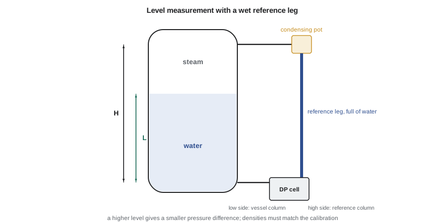
The level indicated depends on the densities assumed for the water and steam in the vessel and for the water in the reference leg. A transmitter calibrated for hot water and steam reads correctly at operating conditions but wrongly when the vessel is cold, and the reverse. The code shows the size of the effect: a level of 1.5 meters at operating conditions would be read as 1.18 meters if the instrument assumed cold water. Plants use separate cold-calibrated and hot-calibrated instruments, or compensate for density using measured pressure. Reference legs are also vulnerable: if the reference leg boils or flashes during a rapid depressurization, it loses water and the instrument reads high, which matters for post-accident level indication. In some BWRs, gas coming out of solution in reference legs during depressurization caused erroneous level readings, leading to design changes and a generic industry response in the 1990s.
Qualification, calibration and response time
Instruments that perform safety functions must meet requirements well beyond those for ordinary process instruments. 10 CFR 50.49 requires environmental qualification of electrical equipment important to safety, with IEEE 323 as the basic method, so that equipment needed during and after an accident will work in the conditions it would face. The technical specifications require channel checks, channel functional tests and channel calibrations at set intervals, and response time testing for reactor protection and engineered safety features channels. Calibration intervals are chosen so that drift between calibrations stays within the allowance used in setpoint calculations, which lesson 8 describes. Since the 2000s, some plants have used online monitoring, comparing redundant transmitters continuously, to justify longer calibration intervals for transmitters that show no drift.
| Measurement | Main sensors | Typical issues |
|---|---|---|
| Temperature | RTDs, thermocouples | response time, self-heating, reference junction |
| Pressure | capacitance or strain-gauge transmitters | impulse lines, qualification, drift |
| Flow | orifice, venturi, elbow taps, ultrasonic | square-law range, density, fouling |
| Level | differential pressure with reference leg | density compensation, reference leg loss |
| Position | limit switches, linear transformers | indication of actual position, not command |
Worked problem
Square-law flow
A heat transport flow transmitter has a full-scale differential pressure of 200 kPa at 100 percent flow. The trip setpoint is 80 percent flow. What differential pressure corresponds to the setpoint, and how large a flow error does a 2 kPa transmitter error cause there?
Show solution
- Δp ∝ flow², so Δp at 80 percent = 200 × 0.8² = 128 kPa.
- Relative Δp error = 2/128 = 1.56 percent.
- Relative flow error = half of that = 0.78 percent of reading, about 0.62 percent of full flow.
Answer: 128 kPa at the setpoint; a 2 kPa error is worth about 0.6 percent of full flow.
Signal validation and drift monitoring
Where several instruments measure the same variable, comparing them gives a powerful check. If four steam generator level channels agree within a small band and a fifth drifts away, the fifth is suspect. Digital control systems use this idea in signal validation: they select the median of three signals, or reject a signal that differs from the others by more than a set amount, so that one failed transmitter cannot upset the controller. Plant computers trend the deviation of each channel from the average of its partners, which reveals slow drift long before it would be found at the next calibration.
Calibration itself has a structure. The as-found reading is recorded before any adjustment, because it shows how much the instrument drifted since the last calibration; the as-left reading after adjustment shows the starting point for the next interval. Trending as-found values across many calibrations shows whether the drift allowance used in setpoint calculations is adequate. Instruments that drift more than expected are replaced or calibrated more often, and an as-found value outside the allowed tolerance on a safety channel is reported and assessed for its effect on operability since the last calibration.
Measurement in harsh environments
Many instruments in a nuclear plant live in conditions that would destroy ordinary electronics: high temperature, humidity and radiation inside containment, vibration on pumps and piping, and in an accident, steam, chemical spray and submergence. Transmitters inside containment are often mounted with their electronics shielded or placed in less harsh areas, and their seals, cables and connectors are part of the qualified assembly. Qualification testing ages samples thermally and by radiation to represent their installed life, then exposes them to a simulated accident in a test chamber, with the instrument required to stay within its accuracy limits throughout. A change in materials, a different cable splice or a missing seal can invalidate the qualification, so installation and maintenance follow strict controls.
Andrea sums up for Hana: “A safety analysis assumes that a trip happens at a certain value within a certain time. Behind that one number is a chain of things that must be true: the sensor is the right one, installed correctly, qualified for the environment, calibrated within tolerance, connected by healthy impulse lines and cables, and processed by a correctly configured channel. Process instrumentation is the work of keeping every link in that chain sound.”
Thermal power and the heat balance
The most important calculation that process instruments feed is thermal power. On the secondary side, the plant computer multiplies each steam generator's feedwater flow by the enthalpy rise from feedwater to steam, using feedwater temperature from RTDs and steam pressure from transmitters, then adds the small corrections for blowdown, pump heat and losses. Feedwater flow is the dominant uncertainty, so plants use their best flow measurements here, often venturis checked against ultrasonic meters, and they watch for fouling of the venturi throat, which makes it read high and leads the plant to run slightly below its licensed power. Because flux signals are calibrated against this heat balance, and trip setpoints in turn depend on the calibrated flux, the accuracy of a few feedwater instruments affects both the plant's output and its safety margins.
Common mistakes
MistakeA transmitter that reads steadily is healthy.
InsteadA blocked impulse line can freeze a reading that looks normal.
MistakeFlow errors are worst at full flow.
InsteadThe square law makes low flows the least accurate.
MistakeA level instrument reads correctly at any temperature.
InsteadDensity assumptions make hot- and cold-calibrated instruments disagree.
Summary and key terms
- RTDs give accurate primary temperatures; thermocouples give rugged wide-range readings.
- Pressure and differential pressure transmitters send 4 to 20 milliampere signals; impulse lines are a common source of error.
- Differential pressure flow follows a square law, accurate at high flow and poor at low flow.
- Level with a wet reference leg depends on assumed densities and on the reference leg staying full.
- Safety instruments are qualified, calibrated and response-time tested to strict schedules.
- RTD
- A resistance temperature detector, usually platinum.
- Thermocouple
- A junction of two metals giving a voltage that depends on temperature difference.
- Impulse line
- A small tube connecting a transmitter to the process.
- Wet reference leg
- A water-filled column kept full by a condensing pot.
- Environmental qualification
- Demonstration that equipment works in accident conditions.
- Loop current step response
- An in-place test of an RTD time constant by self-heating.
Practice problems
Work each problem on paper first, then reveal the answer to check.
Why is a 4 to 20 milliampere signal used?
Show answer
A broken wire reads 0 milliamperes and is distinguishable from a low value.
What is the RTD resistance of a Pt200 at 0 °C?
Show answer
200 ohms.
At 30 percent flow, what fraction of full-scale differential pressure does an orifice give?
Show answer
9 percent.
Why does a wet reference leg read high if it flashes?
Show answer
It loses water, so the reference column is shorter and the difference smaller.
What does a response time test confirm?
Show answer
That a channel acts within the time assumed in the safety analysis.
Lesson quiz · 5 questions
Score 60% or more to complete this lesson.
Create a free account to save your progress, take quizzes and earn a certificate.