
NUC-440 · Lesson 4 of 12 · 20 min
Power control
The rod control system at a Westinghouse plant compares the average reactor coolant temperature with a reference that rises with turbine load, and moves the control banks in or out at a speed that depends on the error. Andrea shows Hana a simulator model in the Meridian Nuclear Engineering lab. “This is where it all comes together,” she says. “Turbine load, coolant temperature, nuclear power, rod speed, the boron trim, the steam dumps and the runbacks. Every second the system decides whether rods should move, and how fast.”
This lesson explains how reactor power is controlled in CANDU and pressurized water reactors, how power control is coordinated with the turbine and steam system, how plants change load, and how automatic power reductions, called stepbacks and setbacks in CANDU plants and runbacks in light-water plants, protect the plant from transients without a reactor trip.
What is being controlled
Reactor power cannot be measured directly. It is inferred from neutron flux, which responds instantly but needs calibration and is affected by flux shape and detector burnup, and from thermal power, calculated from coolant flow and temperature rise or from steam and feedwater flows, which is accurate but slow. Power control systems use neutron signals for speed and calibrate them continuously against thermal power. In a CANDU reactor, out-of-core ion chambers give a fast, accurate bulk signal at low power, and in-core platinum and vanadium self-powered detectors give the zone powers at higher power; in a PWR, out-of-core ion chambers give power range flux, and coolant temperature gives the slower measure that rod control acts on.
The PWR rod control system
In a typical Westinghouse rod control system, the reference temperature is a linear function of turbine first-stage pressure, which is proportional to load. The controller compares the measured average coolant temperature, the mean of the hot and cold leg temperatures in each loop, with this reference. It also adds a power mismatch signal, the difference between nuclear power and turbine load, filtered to respond to rate of change, which makes the system act early when load changes. The combined error sets the direction and speed of rod motion, with a deadband of about 1 kelvin (1.5 °F) so rods do not hunt, and a speed that rises from 8 to 72 steps per minute with the size of the error. The control banks move in a fixed overlapped sequence, and the bank position is limited by the insertion limits in the technical specifications.
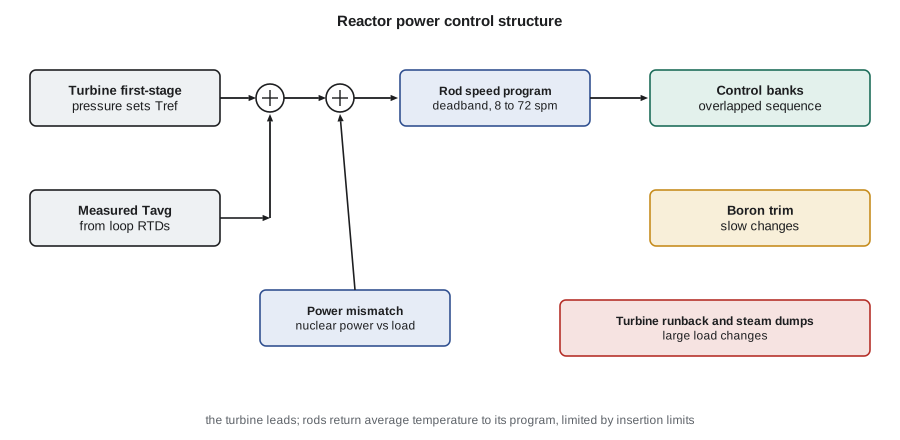
Because the moderator temperature coefficient is strongly negative, the reactor largely follows small load changes by itself: when the turbine takes more steam, the cold leg temperature falls, adding reactivity and raising power. Rod control's job is to bring average temperature back to the reference so that pressurizer level, steam pressure and margins stay where they were designed to be. Boron is used to keep the control banks in a good position as xenon and burnup change. Many plants run with rod control in manual at steady full power, using boron alone to trim temperature, and switch to automatic for load changes.
Coordinating reactor and turbine
In the turbine-leading arrangement, the turbine control valves are positioned by the turbine control system to meet the load demand, and the reactor follows through feedback and rod control. Steam generator pressure therefore falls as load rises, because the average coolant temperature program is a compromise between a constant coolant average temperature, which would make steam pressure fall steeply, and constant steam pressure, which would make coolant temperatures swing widely. Steam dump valves to the condenser absorb sudden load rejections up to a design fraction of full load, and power-operated relief valves on the steam lines protect against higher pressures.
Load following
Most nuclear units in North America run at full power as base load, but many can follow load, reducing power at night or on weekends and responding to the grid. Load following is limited mainly by the fuel and by xenon. Fuel pellets expand and press on the cladding when power rises, so ramp rates and the size of power increases are restricted after a period at lower power to avoid pellet-clad interaction failures. Xenon builds up after a reduction and burns out after an increase, so the controller must find extra reactivity at the worst moment, usually some hours after a reduction when the plant is asked to return to full power.
PWRs in France routinely follow load between full power and about 30 to 50 percent of full power using gray control rods of lower worth, which change power without distorting the flux shape as much as black rods. In North America, the main limits are axial flux difference, which must stay within a band around its target to protect against hot spots, and the amount of boron change the plant can make, since every dilution and boration creates water to process.
# PI power control: point kinetics, temperature feedback and a rate-limited controller follow a load ramp.
beta, lam, Lam = 0.0065, 0.08, 1.0e-4
alpha, K_heat, tau_f = -1.0e-5, 300.0, 5.0
kp, ki = 0.004, 0.0015                 # controller gains (reactivity per unit power error)
rate_lim = 0.0001                      # device speed limit: 0.1 mk per second
dt, t_end = 2.0e-4, 900.0
n = 1.0; C = beta / (Lam * lam); dT = 0.0; rho_dev = 0.0; integ = 0.0
def demand(t):                          # 100% -> 60% at 1% per 10 s, hold, then back
    if t < 100: return 1.0
    if t < 500: return max(0.6, 1.0 - (t - 100) / 1000)
    return min(1.0, 0.6 + (t - 500) / 1000)
worst = 0.0
print(f"{'t (s)':>6s}{'demand':>8s}{'power':>8s}{'device rho (mk)':>17s}")
for k in range(int(t_end / dt) + 1):
    t = k * dt
    e = demand(t) - n
    integ += e * dt
    target = kp * e + ki * integ
    step = max(-rate_lim * dt, min(rate_lim * dt, target - rho_dev))
    rho_dev += step
    rho = rho_dev + alpha * dT
    n += ((rho - beta) / Lam * n + lam * C) * dt
    C += (beta / Lam * n - lam * C) * dt
    dT += (K_heat * (n - 0.6) - dT) / tau_f * dt
    if t > 20: worst = max(worst, abs(e))
    if k % int(100 / dt) == 0:
        print(f"{t:6.0f}{demand(t):8.3f}{n:8.3f}{rho_dev * 1000:17.2f}")
print(f"largest tracking error after start-up: {worst * 100:.2f}% of full power") t (s) demand power device rho (mk)
0 1.000 1.000 0.00
100 1.000 1.000 1.20
200 0.900 0.902 0.83
300 0.800 0.802 0.52
400 0.700 0.702 0.21
500 0.600 0.602 -0.11
600 0.700 0.698 0.40
700 0.800 0.798 0.68
800 0.900 0.898 0.97
900 1.000 0.998 1.26
largest tracking error after start-up: 1.88% of full power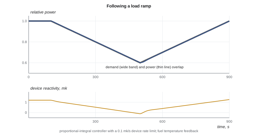
The output shows power tracking the ramp closely, with the largest error under 2 percent of full power, while the device reactivity moves by about 1.3 mk to offset the temperature feedback as power falls and rises. Two features of a real controller appear in the code: the integral term, which holds power on demand despite the feedback, and the rate limit, which represents the maximum speed of the zones or rods. If the ramp is made faster than the device can follow, the error grows and the controller saturates, so real systems limit the operator's demanded ramp rate as well.
Runbacks and steam dumps
A runback is a fast automatic reduction of turbine load, and with it reactor power, triggered by events such as the loss of a feedwater pump or a reactor coolant pump, or a dropped rod. Combined with steam dumps and rapid rod insertion, a runback lets the plant ride through upsets that would otherwise lead to a reactor trip. Some plants can accept a full load rejection without a trip by dumping steam and inserting rods quickly. Runbacks and steam dumps belong to the control system, not to the reactor protection system; they reduce the number of trips and plant transients, while the protection system still watches independently and trips the reactor if the control action is not enough.
| Function | Means | Typical trigger |
|---|---|---|
| Turbine runback | turbine valves close at a set rate | feedwater pump or reactor coolant pump loss |
| Steam dump | valves to condenser | large load rejection |
| Reactor trip | all rods dropped | independent trip parameters (lesson 8) |
Testing and commissioning a power controller
Power control software and tuning are verified on simulators long before they reach the plant, and then tested in stages: at low power, where feedback is weak and the reactor is close to an integrator, then at intermediate and full power. Tests include setpoint steps, ramps, device sequencing, simulated detector failures and the full set of automatic power reductions. Engineers compare the plant's response with the predictions, adjust gains where needed, and record the final settings in controlled documents. Any later change to tuning or logic is treated as a design change, reviewed for its effect on the safety analysis, which assumes certain controller behavior in events such as loss of regulation.
Worked problem
Temperature program
A PWR's reference average coolant temperature rises linearly from 557 °F at zero load to 585 °F at full load. What is the reference at 70 percent load, and what rod action follows if measured average temperature is 578.5 °F?
Show solution
- Tref = 557 + 0.7 × (585 − 557) = 576.6 °F.
- Error = 578.5 − 576.6 = 1.9 °F, outside a 1.5 °F deadband.
Answer: The reference is 576.6 °F; the error is outside the deadband, so rods step in at low speed until the error returns within the band.
Failures of power control
A power control system can fail in several ways, and the plant must be safe in all of them. The controller can lose its input, for example if a detector or temperature channel fails; it can lose its output, if a drive or valve sticks; or its logic can misbehave and drive devices the wrong way. Designers defend against these with redundant inputs and signal validation, which compares several measurements and rejects one that disagrees; with dual or triple controllers and automatic transfer on failure; with limits on device speed and range; and finally with protection systems that do not depend on the controller at all.
In a PWR, a failure of the temperature or turbine pressure input can drive rods continuously in one direction. The plant is protected by rod stops and turbine runbacks in the control system, and by the reactor protection system's overpower and overtemperature ΔT trips. The safety analysis includes uncontrolled rod cluster control assembly bank withdrawal at power and shows that the protection system trips the reactor before departure from nucleate boiling limits are reached.
Who decides how much power
Power control is not only an engineering question. The operator sets the demand within limits set by the licensing basis, the station's operating policies and the grid operator's instructions. Each change of power is planned and recorded, and some changes, such as raising power after a long period at low power, follow conditioning rules set by the fuel designers. Andrea stresses that the best control system is one that makes the operator's intended action easy and safe, and makes unintended action difficult: confirmations before large changes, rate limits on demand, and clear indication of which mode the controller is in.
Hana notes that the ideas of lesson 1 appear everywhere in the power controller: integral action to hold power on demand, rate limits to avoid windup, feedforward from load signals, gain scheduling with power and separate protection. The specific devices and conventions differ between CANDU and light-water plants, but the loop is the same.
There is also an economic side. A unit that trips loses hours or days of production and stresses its equipment with a thermal cycle; a unit that rides through an upset on an automatic power reduction keeps generating. Utilities therefore track trips per year as a key performance indicator, and much of the effort spent on tuning and testing power control is justified by the trips it avoids. The regulator watches the same indicator for a different reason: frequent unplanned trips challenge the safety systems and can signal weaknesses in equipment or operations.
Power controllers also hand over between modes during start-up. At very low power the operator raises power manually in small steps, watching the log rate; as power reaches the range where the controller's measurements are accurate, control is transferred to automatic, and at higher powers the measurement source changes from ion chambers or intermediate range channels to power range or in-core signals. Each transfer is a point where a mismatch between signals could cause a bump, so the logic checks that the incoming signal agrees with the outgoing one before it accepts the transfer.
Common mistakes
MistakeNeutron flux is reactor power.
InsteadFlux is a fast indicator that must be calibrated against thermal power.
MistakeA stepback is a reactor trip.
InsteadStepbacks and runbacks are control actions; trips are protection actions.
MistakeLoad following is limited mainly by the controller.
InsteadIt is limited mainly by fuel behavior and xenon.
Summary and key terms
- Power control uses fast neutron signals calibrated against slower thermal power.
- PWR rod control holds average coolant temperature on a load program, with boron for slow changes.
- The turbine leads and the reactor follows through feedback and rod control.
- Load following is limited by fuel conditioning and xenon.
- Automatic power reductions avoid trips but do not replace protection.
- Reference temperature
- The average coolant temperature program, set by turbine load.
- Power mismatch
- The difference between nuclear power and turbine load, used to anticipate.
- Axial flux difference
- The difference between top and bottom core power.
- Runback
- A fast automatic reduction of turbine load and reactor power.
- Steam dump
- Valves that send steam to the condenser on a load rejection.
- Thermal power
- Reactor power calculated from coolant or steam conditions.
Practice problems
Work each problem on paper first, then reveal the answer to check.
Why are neutron signals calibrated against thermal power?
Show answer
Flux responds instantly but its relation to power drifts with flux shape and detector burnup.
Why does PWR power follow small load changes almost by itself?
Show answer
The negative moderator coefficient adds reactivity as the cold leg cools.
What limits power increases after a period at low power?
Show answer
Pellet-clad interaction and xenon.
Why is a rate limit included in the controller model?
Show answer
Real devices move at a maximum speed.
Who must still act if an automatic power reduction fails to stabilize the plant?
Show answer
The independent protection system.
Lesson quiz · 5 questions
Score 60% or more to complete this lesson.
Create a free account to save your progress, take quizzes and earn a certificate.