
LVT-320 · Lesson 7 of 12 · 20 min
Wi-Fi design for capacity and roaming
A Wi-Fi network can show green on every coverage heatmap and still fail its users. Brightwater discovered this at its first all-hands meeting in the new office: four hundred people in one open area, every laptop and phone on Wi-Fi, and the video call stuttered for everyone although the signal was excellent. At St. Brendan's, the problem is different: a nurse walking from a patient room to the medication room while on a badge call must roam between access points without the call dropping. Designing for coverage alone is not enough; a modern design starts from capacity and roaming. This lesson covers airtime and capacity, counting devices and their demands, sizing the number of access points, cell size and overlap, roaming and the standards that help it, high-density areas, and designs for voice and location services.
Airtime is the resource
Wi-Fi is a shared medium. On each channel, only one radio can transmit at a time in any area where they can hear each other; the others wait. The resource that runs out is airtime, the fraction of each second the channel is busy. A device sending at a high data rate uses little airtime for its data; a slow device at the edge of coverage, or an old one that only supports low rates, uses much more for the same amount of data. Management traffic uses airtime too: every access point broadcasts beacons about ten times a second for each network name it advertises, at the lowest data rate the network allows. A design with ten network names on twenty access points that all hear each other can spend a large share of the airtime on beacons before any user sends data.
Two settings that installers sometimes see in configuration reviews matter for airtime. Disabling the lowest data rates, so that beacons and the slowest clients use at least a moderate rate, reduces beacon airtime and stops distant clients from clinging at very low rates. Limiting the number of network names, typically to three or four, keeps beacon overhead down. Both are network team decisions, but the survey data the installer collects shows whether they are working.
Counting devices and demand
Capacity design starts with a count: how many devices of each type will use each area, at the busiest time, and what each needs. Frank's worksheet for St. Brendan's east wing lists, for each floor, staff laptops and workstations on wheels, nurse badges, staff phones, infusion pumps and monitors, location tags, and guest devices, with the throughput each needs and how many are active at once. Most devices are idle most of the time, so the design uses an active ratio, the share transmitting at once, from the owner's experience or the device maker's guidance. Video calls and imaging workstations dominate the throughput; badges and tags dominate the device count.
# Capacity-based access point count for one area, compared with the coverage-based count
import math
devices = [  # type, count, active share, throughput when active (Mb/s)
    ("Staff laptops and WOWs", 60, 0.5, 8.0),
    ("Nurse voice badges",     80, 0.3, 0.2),
    ("Staff phones",           90, 0.3, 1.0),
    ("Infusion pumps",         120, 0.2, 0.1),
    ("Patient guest devices",  70, 0.4, 3.0),
]
need = sum(n * a * t for _, n, a, t in devices)
RADIO_GOODPUT = 120.0     # Mb/s a radio can deliver to a realistic client mix (illustrative)
RADIOS_PER_AP = 2         # 5 and 6 GHz radios serving clients
per_ap = RADIO_GOODPUT * RADIOS_PER_AP * 0.6   # keep utilization at or below 60 percent
cap_aps = math.ceil(need / per_ap)
AREA = 28000             # sq ft
COVER = 2370           # sq ft one access point covers at the voice target, from the survey
cov_aps = math.ceil(AREA / COVER)
print(f"Demand at the busiest hour: {need:.0f} Mb/s")
for d, n, a, t in devices:
    print(f"  {d:24s} {n:4d} x {a:.1f} active x {t:4.1f} Mb/s = {n*a*t:6.1f} Mb/s")
print(f"Access points for capacity: {cap_aps}")
print(f"Access points for coverage: {cov_aps}")
print(f"Design count: {max(cap_aps, cov_aps)} (the larger of the two)")Demand at the busiest hour: 358 Mb/s Staff laptops and WOWs 60 x 0.5 active x 8.0 Mb/s = 240.0 Mb/s Nurse voice badges 80 x 0.3 active x 0.2 Mb/s = 4.8 Mb/s Staff phones 90 x 0.3 active x 1.0 Mb/s = 27.0 Mb/s Infusion pumps 120 x 0.2 active x 0.1 Mb/s = 2.4 Mb/s Patient guest devices 70 x 0.4 active x 3.0 Mb/s = 84.0 Mb/s Access points for capacity: 3 Access points for coverage: 12 Design count: 12 (the larger of the two)
For a patient floor, coverage usually sets the count: the walls are many and the device demand is moderate. For Brightwater's open meeting area, capacity sets it: four hundred laptops in one room would need many more radios than the room's size suggests. The design count is always the larger of the two, and the design then checks that the extra access points in a dense area do not interfere with each other.
Cell size and overlap
Each access point radio covers a cell, the area where clients receive it above the design threshold. In a coverage design, cells overlap enough that every location has a primary and a secondary access point above the targets, so a client can roam before its current access point becomes too weak. Typical voice-grade designs aim for 15 to 20 percent overlap at −67 dBm. But overlap on the same channel is co-channel contention, which reduces capacity. The designer resolves this with channel reuse: neighboring cells use different channels, and each channel is reused only far enough away to be heard weakly.
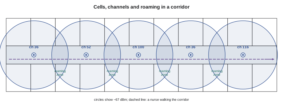
Smaller cells, more access points at lower power, give more capacity per square meter and better roaming, because each client is always close to an access point and the channels can be reused often. The limit is co-channel contention: if cells are so small and numerous that each channel is heard strongly in many places, capacity falls again. In 6 GHz, with many channels, designers can make cells smaller before that limit arrives.
Roaming
In Wi-Fi, the client decides when to roam, not the access point. Each client has its own roaming logic, usually looking for a better access point when its current signal falls below a threshold, often around −70 to −75 dBm. Roaming involves scanning for candidates, choosing one, re-authenticating and moving the session. With enterprise security, full re-authentication can take hundreds of milliseconds, long enough to break a voice call. Three amendments help. 802.11k lets the access point give the client a neighbor report, a list of nearby access points and their channels, so the client scans less. 802.11v lets the network suggest that a client move to a better access point. 802.11r, fast BSS transition, lets the client prepare its security keys with the new access point before moving, reducing the switch to tens of milliseconds.
Roaming performance is measured, not assumed. During the east wing validation, Maya walks the corridors with a badge on a test call while a second device records roam events and the time each takes. The requirement is no dropped calls and roams faster than the badge maker's limit, typically under 50 to 150 milliseconds; roams that take longer show where the overlap is thin or a setting is wrong.
# Roaming log review: find slow roams and the access points involved
log = [  # time (s), from AP, to AP, roam time (ms), rssi before (dBm)
    (12.1, "3E-02", "3E-03", 38, -71), (48.6, "3E-03", "3E-05", 42, -72), (75.0, "3E-05", "3E-06", 310, -82),
    (101.4, "3E-06", "3E-08", 35, -70), (133.9, "3E-08", "3E-09", 260, -80), (160.2, "3E-09", "3E-11", 41, -71),
]
LIMIT = 100
slow = [r for r in log if r[3] > LIMIT]
print(f"roams {len(log)}, slow {len(slow)}, average {sum(r[3] for r in log)/len(log):.0f} ms")
for t, a, b, ms, rssi in slow:
print(f" {t:6.1f} s {a} -> {b}: {ms} ms, signal had fallen to {rssi} dBm before roaming (thin overlap?)")roams 6, slow 2, average 121 ms
75.0 s 3E-05 -> 3E-06: 310 ms, signal had fallen to -82 dBm before roaming (thin overlap?)
133.9 s 3E-08 -> 3E-09: 260 ms, signal had fallen to -80 dBm before roaming (thin overlap?)The two slow roams both began after the signal had fallen to −80 dBm or below, which suggests thin overlap between those access points rather than a security setting. The survey heatmaps for that stretch of corridor, between the elevator lobby and the medication room, confirm a weak secondary signal; the fix is an adjusted power plan or an additional access point.
High-density areas
Lecture halls, meeting rooms, cafeterias, auditoriums and arenas hold many devices in a small area. Designs for them use more access points at low power, often with directional antennas or ceiling-mounted access points with narrow patterns that keep each cell small, and narrow channels so more channels are available for reuse. Under-seat or floor-mounted access points are used in arenas, letting the bodies of the audience limit each cell. At Brightwater, the all-hands problem was solved by adding six access points over the open area, set to low power, with 20 MHz channels at 5 GHz and 80 MHz at 6 GHz, so the room's devices were spread across many radios rather than crowding a few.
Density also changes the client mix. A meeting room fills with laptops that all connect at once when a meeting starts, and phones that roam in from the corridor. Band steering, where the network encourages dual-band clients to use 5 or 6 GHz rather than 2.4 GHz, and load balancing between access points help spread the load. The installer's contribution is accurate placement: an access point mounted two meters from its design position in a dense room changes the overlap for its neighbors.
Voice, location and IoT
Different services set different targets. Voice needs the strongest and most consistent signal, typically −67 dBm primary with a secondary at −70, SNR of 25 dB, low channel utilization and fast roaming. Real-time location systems that use Wi-Fi signal strength need several access points, often three or four, heard at good levels everywhere, so that a tag's position can be worked out; some use Bluetooth beacons or ultra-wideband anchors instead, and those have their own placement rules. IoT sensors usually need little throughput but must be reached in odd places, such as freezers, pump rooms and outdoor equipment pads. The device list from the start of the design tells the designer which targets apply where.
| Service | Primary | Secondary | SNR | Other needs |
|---|---|---|---|---|
| Web and email | −70 dBm | Not required | 20 dB | Moderate capacity |
| Voice and video calls | −67 dBm | −70 dBm | 25 dB | Fast roaming, low utilization |
| Wi-Fi location | −67 dBm | Three or more APs at −75 dBm | 25 dB | AP geometry around the area |
| IoT sensors | −75 dBm | Not required | 15 dB | Coverage in unusual places |
Worked problem
The meeting room that collapsed at 10 o'clock
Brightwater's boardroom works well all day except at the 10:00 weekly meeting, when thirty people join video calls and audio breaks up. The survey shows −55 dBm from the room's one access point. What is happening and what should be changed?
Show solution
- The signal is strong, so coverage is not the problem.
- Thirty video calls at about 3 Mb/s each, plus other traffic, need roughly 100 Mb/s; with many clients on one radio, contention and retries consume much of the airtime.
- The access point's 2.4 GHz radio also carries some phones at low rates, using more airtime.
- The fix is capacity: add a second access point in the room at low power on a different channel, encourage clients onto 5 and 6 GHz, and confirm with an active survey during the next meeting that utilization stays below about 60 percent.
Answer: The room ran out of airtime, not signal; more radios on more channels, at low power, restore performance.
Checking a design before it is built
Before the east wing design is approved, Frank asks Maya to check it the way a reviewer would. She confirms that every room on the requirements list falls inside a cell at the required primary and secondary levels, that no access point hears more than two others on its own channel above the design threshold, and that the number of access points in each area matches the device count from the capacity worksheet. She also checks the practical details the software does not care about: that each access point sits where a ceiling tile can be lifted to reach it, that none is above a medical gas outlet or a sprinkler head, and that each has a cable route back to a telecommunications room within the length limit.
Common mistakes
MistakeDesigning only for coverage.
InsteadCount devices and demand, and use the larger of the coverage and capacity counts.
MistakeAdvertising many network names.
InsteadKeep network names few; each one adds beacon airtime on every access point.
MistakeAssuming the access point decides when a client roams.
InsteadThe client decides; design overlap and enable 802.11k, v and r to help.
MistakeFilling a dense room with high-power access points.
InsteadUse more access points at low power with narrow cells and channels.
MistakeMoving an access point a few meters for convenience.
InsteadMount it where designed; small moves change overlap and capacity.
Summary and key terms
- Airtime, not signal, is the resource that runs out on a busy channel.
- Low data rates and many network names waste airtime.
- Capacity design counts devices, active shares and throughput; the design uses the larger of the capacity and coverage counts.
- Overlapping cells give roaming zones; channel reuse keeps co-channel contention low.
- Clients decide when to roam; 802.11k, v and r make roaming faster and smarter.
- High-density areas need more access points at low power, narrow cells and narrow channels.
- Voice, location and IoT services each set their own coverage targets.
- Airtime
- The share of time a channel is busy with transmissions.
- Active ratio
- The share of devices transmitting at the same time.
- Cell
- The area where an access point is received above the design threshold.
- Channel reuse
- Assigning the same channel to access points far enough apart not to interfere strongly.
- Fast BSS transition
- 802.11r: preparing security keys before roaming to shorten the switch.
- Neighbor report
- 802.11k: a list of nearby access points given to a client.
- Band steering
- Encouraging dual-band clients onto the higher bands.
Practice problems
Work each problem on paper first, then reveal the answer to check.
What sets the design access point count?
Show answer
The larger of the coverage and capacity counts.
Who decides when a Wi-Fi client roams?
Show answer
The client.
Which amendment shortens re-authentication when roaming?
Show answer
802.11r, fast BSS transition.
What utilization limit does the Brightwater fix aim for?
Show answer
About 60 percent or less.
Lesson quiz · 5 questions
Score 60% or more to complete this lesson.
Create a free account to save your progress, take quizzes and earn a certificate.