
LVT-320 · Lesson 4 of 12 · 19 min
Antennas and propagation indoors
The link budget in lesson 3 treated the building as a single number for wall loss. Real buildings are not that tidy. Signals bounce off steel, slip through doorways, fade in and out as people walk past, and disappear behind elevator shafts. The antenna that launches the signal shapes all of this, because it decides where the energy goes in the first place. This lesson covers antenna types and patterns, polarization, how signals propagate indoors, multipath and MIMO, attenuation by building materials, and the special problems of hospitals, warehouses and parking garages, the three kinds of space Cobalt Line is working in this term.
Antenna patterns
An antenna's radiation pattern shows how strongly it radiates in each direction. Patterns are drawn as two slices: the horizontal or azimuth pattern, seen from above, and the vertical or elevation pattern, seen from the side. An omnidirectional antenna radiates equally in all horizontal directions, like a doughnut around the antenna; a directional antenna concentrates its energy into a beam. The beamwidth is the angle between the points where the power has fallen by 3 dB from the peak. The front-to-back ratio compares the power in the main direction with the power radiated backward; a donor antenna needs a high front-to-back ratio so that it hears the distant tower and not the building's own antennas.
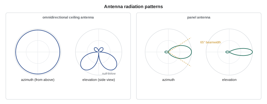
The patterns explain installation rules that otherwise seem arbitrary. A ceiling-mount omnidirectional antenna radiates mostly outward and down, with a weaker spot straight below, so it is mounted in the middle of the area it serves, away from metal ducts that would reflect and distort its pattern. A panel antenna mounted at the end of a long corridor throws its beam down the corridor. A donor antenna on the roof is aimed precisely at the serving tower, using a compass bearing and a measured signal peak, and its back is turned to the building's interior antennas.
Common antenna types
| Type | Typical gain | Use in buildings |
|---|---|---|
| Ceiling omni (dome) | 2 to 4 dBi | DAS coverage in rooms and corridors |
| Wall or ceiling panel | 6 to 10 dBi | Corridors, warehouse aisles, garages |
| Yagi | 8 to 15 dBi | Donor antennas, point-to-point links |
| Access point internal | 3 to 6 dBi | Wi-Fi in offices, classrooms, patient rooms |
| Access point external directional | 6 to 14 dBi | High ceilings, stadium seating, outdoor |
| Radiating (leaky) cable | Coupling loss, not gain | Tunnels, stairwells, long garages |
Wide-band antennas cover many bands with one element, which is why a single DAS antenna can serve several carriers and the public safety bands at once. Their gain and pattern change with frequency, so the designer reads the data sheet for each band. Radiating cable, also called leaky feeder, is coax with slots cut in its outer conductor so that it radiates a little energy along its whole length; instead of gain, its data sheet gives coupling loss, the loss between the cable and a receiver a stated distance away.
Polarization
The polarization of a wave is the direction of its electric field. A vertical whip radiates vertically polarized waves. A receiving antenna works best when its polarization matches the wave's; a vertical antenna receiving a horizontally polarized signal can lose 20 dB or more in an open field. Indoors, reflections twist polarization, so the mismatch is smaller, but designers still match where they can: public safety and cellular systems are mostly vertical, and many DAS antennas and modern cellular panels use two slanted polarizations, plus and minus 45 degrees, so that two signal streams can share an antenna. Phones and laptops are held at every angle, which is one reason Wi-Fi access points use several antennas with different orientations.
How signals travel indoors
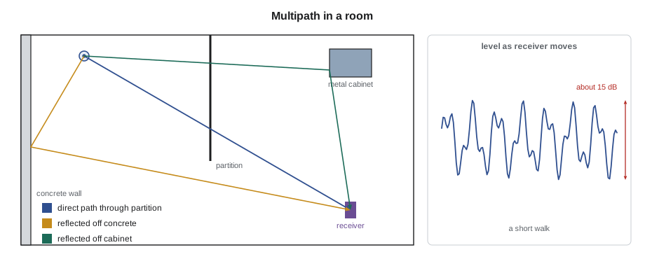
Indoors, a signal reaches the receiver along many paths at once: directly through open space or walls, reflected from floors, ceilings and metal, diffracted around corners and doorways, and scattered from small objects. The paths have different lengths, so the copies arrive at slightly different times and phases. Where they add in phase, the signal is strong; where they cancel, it fades. Moving the receiver a few centimeters, half a wavelength, can change the signal by 10 to 20 dB. This is multipath fading, and it is why survey meters average many samples rather than reading a single value, and why a signal that is fine for a stationary laptop can drop for a walking user.
Indoor path loss is often modeled with a path loss exponent: in free space, loss rises with 20 times the logarithm of distance, an exponent of 2; in an open-plan office it might be about 2 to 3; in a building with many walls, 3 to 4 or more. Corridors can act as waveguides, carrying signal with an exponent below 2 along their length while rooms off the corridor fall away quickly. Survey software uses models like these, adjusted with measured wall losses, to predict coverage before installation.
Multipath as an advantage: MIMO
Older radios suffered from multipath; modern ones use it. Multiple-input multiple-output, MIMO, uses several antennas on each side of the link. Because each antenna sees a slightly different combination of paths, the radios can separate several data streams sent on the same frequency at the same time, multiplying throughput. Wi-Fi access points commonly have two to eight antennas per band; multi-user MIMO lets an access point send different streams to several clients at once, and beamforming adjusts the phase at each antenna to steer energy toward a client. In LTE and 5G, MIMO is why carriers want DAS antennas with two or four ports. For the installer, MIMO means more cables per antenna location and careful labeling, because swapping two MIMO ports may not stop the system working but can reduce its performance.
Building materials
Each material between transmitter and receiver adds loss, and the loss rises with frequency. The values in the table are typical figures for planning, not measurements; real walls vary with thickness, moisture, reinforcement and construction. Designers measure the actual walls of a building whenever they can, by placing a test transmitter on one side and a meter on the other, and enter the measured values into their survey software.
| Material | About 800 MHz | About 2.4 GHz | About 5 to 6 GHz |
|---|---|---|---|
| Drywall partition | 1 to 2 dB | 2 to 3 dB | 3 to 5 dB |
| Interior glass | 1 to 2 dB | 2 to 3 dB | 3 to 4 dB |
| Wood door | 2 dB | 3 dB | 4 dB |
| Brick wall | 4 to 6 dB | 6 to 10 dB | 10 to 15 dB |
| Concrete wall, 8 in | 8 to 12 dB | 12 to 18 dB | 15 to 25 dB |
| Low-emissivity glass | 15 to 25 dB | 20 to 30 dB | 25 to 40 dB |
| Elevator shaft or steel fire door | 20 dB or more | 25 dB or more | 30 dB or more |
| Lead-lined wall (imaging) | Very high | Very high | Very high |
# Estimate the signal in a room from an access point, through a list of materials
import math
LOSS = {  # dB at 5.5 GHz (illustrative planning values)
    "drywall": 4, "glass": 3, "wood door": 4, "brick": 12, "concrete": 20, "fire door": 30, "lead wall": 50,
}
def fspl(d_m, f_mhz): return 20 * math.log10(d_m) + 20 * math.log10(f_mhz) - 27.55
EIRP = 20.0                         # dBm, access point at 5.5 GHz
rooms = [  # room, distance (ft), materials crossed
    ("Patient room 3.14", 20, ["drywall"]),
    ("Patient room 3.16", 36, ["drywall", "drywall"]),
    ("Nurse station",     30, ["glass"]),
    ("Stairwell C",       46, ["concrete", "fire door"]),
    ("CT scanner room",   39, ["lead wall"]),
]
for room, dist, mats in rooms:
    d_m = dist * 0.3048
    rx = EIRP - fspl(d_m, 5500) - sum(LOSS[m] for m in mats)
    verdict = "ok for voice" if rx >= -67 else ("data only" if rx >= -75 else "needs coverage")
print(f"{room:18s} {dist:5.1f} ft {'+'.join(mats):20s} {rx:6.1f} dBm {verdict}")Patient room 3.14 20.0 ft drywall -47.0 dBm ok for voice Patient room 3.16 36.0 ft drywall+drywall -56.1 dBm ok for voice Nurse station 30.0 ft glass -49.5 dBm ok for voice Stairwell C 46.0 ft concrete+fire door -100.2 dBm needs coverage CT scanner room 39.0 ft lead wall -98.8 dBm needs coverage
The estimate confirms what the east wing's design already assumes: the stairwells and the imaging suite cannot be covered from corridor access points. Stairwells get their own coverage, and the imaging rooms, shielded by design to keep X-rays in, get access points and DAS antennas inside them, with cables passing through the shielding at penetrations approved by the medical physicist who certifies the shielding.
Hospitals
Hospitals combine almost every hard case. Concrete shear walls and floors are thick; imaging rooms are lined with lead or, for MRI, enclosed in a copper or steel radio-frequency cage that must not be compromised; elevator banks and mechanical shafts break up floors; and the devices that must work are life-critical. MRI suites are a special case: the magnet room's RF shield exists to keep outside radio out of the scanner, so nothing may penetrate it except through filters and waveguides provided by the MRI vendor, and ferromagnetic tools and equipment must never enter the magnet room. Maya's crew will not work inside the MRI room at St. Brendan's at all; coverage stops at its door.
Hospitals also care about interference to medical equipment. Modern devices are designed to tolerate the fields from phones and access points, and hospital policies set minimum distances where needed. The owner's clinical engineering department reviews the wireless design, and installers follow their rules for work near patients and equipment, including infection control measures when opening ceilings in occupied areas.
Warehouses and garages
Warehouses look simple, one big room, but their contents change everything. Racking full of metal, liquids or paper absorbs and reflects signal, so coverage measured in an empty building fails when the racks are stocked. At Hartwell, Frank's design puts directional antennas at the ends of aisles and access points high on the racking uprights, aimed down the aisles, rather than relying on ceiling access points far above the steel. Seasonal stock levels matter too: a survey done in a slow month can mislead.
Underground parking garages are concrete boxes, often below grade, with no windows and long ramps. Signals from outside barely reach them. Ceiling-mounted panel antennas aimed along driving aisles, or radiating cable run along the ceiling, are common solutions. Garage ceilings carry sprinklers, lighting and ventilation ducts, and cars park under the antennas, so mounting heights and clearances must be planned with the other trades. Juniper Point's three-level garage, which needs public safety coverage, is the subject of lessons 9 and 10.
Worked problem
Coverage that failed after the racks were filled
Hartwell's operations manager reports that handheld scanners drop their Wi-Fi connection in aisles 14 to 18 since the new stock arrived, though Cobalt Line's survey a year ago showed −62 dBm or better everywhere. The access points have not changed. What should Maya check, and what is the likely fix?
Show solution
- The survey was done when aisles 14 to 18 held lightweight packaging; they now hold canned goods and drums of liquid, which absorb far more signal.
- Maya surveys the aisles again with the racks full and finds −78 to −82 dBm in the middle of the aisles, too weak for the scanners' roaming.
- The ceiling access points are high above the racks, and the stock now blocks the paths into the aisles.
- The fix is to add access points or directional antennas aimed down those aisles, designed from the new survey, and to agree with Hartwell that future surveys are done at peak stock.
Answer: The building's contents changed the radio environment; a new survey at peak stock drives the redesign of those aisles.
Common mistakes
MistakeMounting a ceiling antenna against a metal duct.
InsteadKeep antennas clear of large metal, which distorts the pattern.
MistakeAiming a donor antenna by eye.
InsteadAim it by bearing and peak measured signal, with its back to the indoor antennas.
MistakeSwapping MIMO ports carelessly.
InsteadLabel and connect MIMO ports exactly as designed.
MistakeUsing table values as if they were measurements.
InsteadMeasure real walls and enter the measured losses into the design.
MistakePenetrating an MRI room's RF shield for a cable.
InsteadNever; only the MRI vendor's filters and waveguides may pass through it.
Summary and key terms
- Antenna patterns show where energy goes; beamwidth and front-to-back ratio describe directional antennas.
- Omnidirectional ceiling antennas serve rooms; panels serve corridors and aisles; Yagis and high-gain panels serve as donors.
- Matching polarization matters; slant-polarized and multi-antenna designs carry several streams.
- Indoor signals arrive by many paths and fade over half-wavelength distances.
- MIMO turns multipath into extra capacity, so antennas have several ports to label and connect correctly.
- Material losses rise with frequency; concrete, coated glass, steel and lead are the hardest.
- Hospitals, warehouses and garages each need designs that account for their particular structures and contents.
- Radiation pattern
- A plot of how strongly an antenna radiates in each direction.
- Beamwidth
- The angle between the half-power (−3 dB) points of a directional antenna.
- Front-to-back ratio
- The ratio of power in an antenna's main direction to the power radiated backward.
- Polarization
- The orientation of a wave's electric field.
- Multipath
- Reception of several copies of a signal by different paths.
- MIMO
- Multiple-input multiple-output: several antennas at each end carrying several data streams.
- Radiating cable
- Slotted coax that radiates along its length, used in tunnels and garages.
Practice problems
Work each problem on paper first, then reveal the answer to check.
A panel antenna has a beamwidth of 65 degrees. What does the beamwidth tell you?
Show answer
The angle between the directions where its power is 3 dB below the peak.
Why do survey meters average many samples?
Show answer
Multipath makes the level vary over short distances.
About how far must a 5 GHz receiver move to pass from a peak to a null?
Show answer
About a quarter to a half wavelength, 0.6 to 1.2 in.
Why survey a warehouse at peak stock?
Show answer
Full racks absorb and reflect far more signal than empty ones.
Lesson quiz · 5 questions
Score 60% or more to complete this lesson.
Create a free account to save your progress, take quizzes and earn a certificate.