
IRW-330 · Lesson 2 of 12 · 23 min
Reading the metal building drawings
▶ Video coming soon A video version of this lesson is on the way.
The second tab in Corwin's binder held the drawings. A metal building drawing set looks different from the structural drawings Shay had seen at Ashcroft. It is produced by the manufacturer's software, it uses the same layout and symbols from job to job, and it is written for the erector. Corwin's crew read it the way a mechanic reads a parts book: to find each piece, where it goes and what it bolts to. This lesson explains what is in a metal building drawing set, how to read each sheet, and how to check the drawings against the building being built.
The drawing set
A manufacturer's drawing set is usually issued twice. The first issue, the approval drawings, goes to the builder and owner before the order is released for fabrication, so they can confirm the size, framed openings, colors and accessories. Once the builder signs and returns them, any changes are made and the steel is fabricated. The second issue, the erection drawings, ships with the building and shows how to assemble it. An erector must work from the erection drawings, not the approval set, because changes are made between the two.
A typical erection drawing set contains these sheets, in roughly this order.
| Sheet | What it shows | Who uses it most |
|---|---|---|
| Cover sheet and general notes | Building size, design loads, codes, bolt and material specifications, notes for the erector | Everyone; read first |
| Anchor rod plan | Anchor rod locations, sizes, projections and the column reactions | Concrete contractor and erector |
| Roof framing plan | Frame lines, purlins, eave struts, roof bracing and flange braces | Erector |
| Sidewall and endwall framing elevations | Columns, girts, wall bracing, framed openings and base details | Erector |
| Cross sections | Each rigid frame type with its pieces, connections and bolt counts | Erector |
| Sheeting and trim plans | Panel layout, panel lengths, trim pieces and their locations | Erector and sheeting crew |
| Details | Connection, bracing, base, opening, trim and accessory details | Erector |
| Bills of material | Every piece by part number, quantity, length and weight | Whoever checks the shipment |
The Brannock set from Northfield had fourteen sheets. Sheet E1 was the cover sheet, E2 the anchor rod plan, E3 the roof framing plan, E4 and E5 the sidewalls, E6 and E7 the endwalls, E8 the cross sections, E9 to E11 the sheeting and trim, E12 and E13 the details and E14 the bill of material for the bolts and fasteners. The parts list for the steel pieces came as a separate shipping list.
The cover sheet and general notes
Corwin's first rule for any metal building is to read the whole cover sheet before touching the steel. It lists the building's dimensions, eave height and roof slope, the code and edition the building was designed to, the design loads, the material grades, and the general notes. The general notes are where the manufacturer tells the erector things that apply to the whole building: the bolt grades and tightening method, which connections are pretensioned, how the frames must be braced during erection, which panels or members must not be cut, and what to do about missing or damaged parts.
The Brannock cover sheet gave a ground snow load, a rain load and an ultimate wind speed taken from the Ohio Building Code and ASCE 7 for the site, a risk category for an agricultural building with low human occupancy, and a collateral load for future lights. It also had a note in capital letters: TEMPORARY BRACING IS THE RESPONSIBILITY OF THE ERECTOR. FRAMES ARE NOT STABLE UNTIL ALL PERMANENT BRACING, PURLINS, GIRTS AND FLANGE BRACES ARE INSTALLED.
Shay noticed that the notes also said, in plainer type, that field modifications such as cutting holes in frame members, flame cutting or welding to any member were not allowed without written approval from the manufacturer's engineer. Corwin underlined it. "That one gets broken more than any other," he said. "Somebody wants a hole for a conduit, takes a torch to a rafter web, and voids the warranty and maybe the building."
Grid lines, frame lines and orientation
Metal building drawings use a grid. Frame lines run across the building and are numbered from 1 at one endwall to the last frame line at the other. Lines along the building are lettered, usually A for one sidewall and the last letter for the other, with intermediate letters for any interior columns or endwall columns. On a clear-span building with no interior columns, the sidewalls are often A and B, and the endwall columns have their own numbering.
The drawings also show the building's orientation with a north arrow or with the sidewall names, such as front sidewall and back sidewall, or left and right endwall as seen from a stated side. This matters because openings, bracing bays and accessories are located by wall. An erector who reverses the building on the slab puts every door on the wrong wall.
Worked problem
Checking the overall length
The roof framing plan of the Brannock building shows six bays, each 20 ft, from frame line 1 to frame line 7. The general notes give the building length as 120 ft out to out of the girts. Do the bays add up to the stated length?
Show solution
- Bay total = 6 × 20 = 120 ft.
- The stated length is measured to the outside of the endwall girts, which is also where the bay dimensions are taken at the endwalls.
- Check: 120 ft = 120 ft.
Answer: The bays add up. On metal buildings, the end bays are dimensioned to the outside of the endwall girts, not to the endwall column centerlines, so the end bays look different on the anchor rod plan from the interior bays. A chain that does not add up is reported before the anchor rods are set, not after.
The anchor rod plan and the reactions
The anchor rod plan, sometimes still called the anchor bolt plan, is the first sheet the concrete contractor uses and the one the erector checks before anything else happens. It shows every column location on the slab, dimensioned from the building lines, with a detail for each column type showing the number of rods, their diameter, their spacing, their projection above the concrete and their position relative to the building line. Lesson 3 covers the checks the erector makes.
The anchor rod plan also carries a table of column reactions: the forces each column puts on the foundation under each load case. Metal building reactions are a surprise to people used to conventional buildings, because a clear-span rigid frame pushes outward at its column bases. Under roof load, the rafters try to flatten, which pushes the column feet apart. The foundation has to resist that horizontal thrust, either through the footing, through hairpin rebar into the slab, or through a tie rod buried across the building.
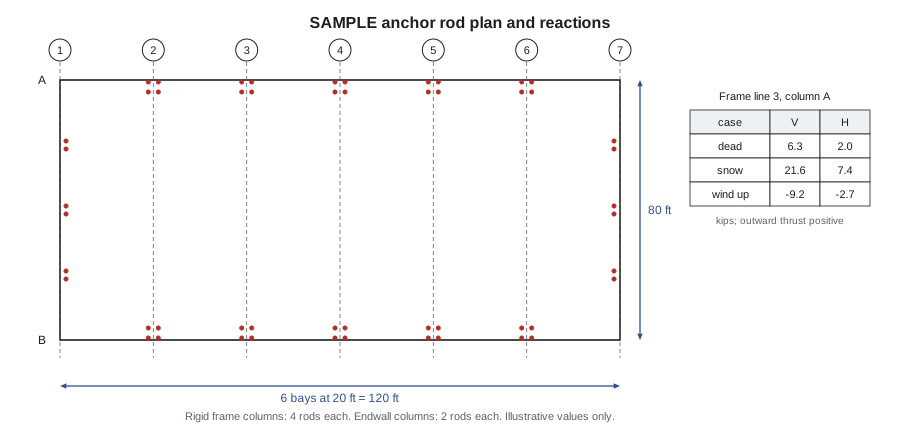
| Load case | Vertical (kips) | Horizontal, outward (kips) |
|---|---|---|
| Dead | 6.3 | 2.0 |
| Snow | 21.6 | 7.4 |
| Wind, uplift case | −9.2 | −2.7 |
| Wind, lateral case | ±4.0 | ±4.7 |
Worked problem
Reading the reactions
Using the SAMPLE table, what vertical load and outward thrust does one interior column put on its footing under dead plus snow? Under wind uplift, what does the negative vertical reaction mean for the anchor rods?
Show solution
- Dead plus snow vertical = 6.3 + 21.6 = 27.9 kips down.
- Dead plus snow horizontal = 2.0 + 7.4 = 9.4 kips outward.
- Under wind uplift the column pulls up by 9.2 kips, which the dead load only partly offsets; the anchor rods must hold the column down.
Answer: About 27.9 kips down and 9.4 kips outward under dead plus snow. The engineer combines the cases with load factors; the erector's interest is that the rods are not just for locating the column. They carry uplift and shear, so their size, embedment and projection must be exactly as drawn.
The framing plans and elevations
The roof framing plan shows the roof as if seen from above with the panels removed. It shows each purlin line with its part number, the eave struts, the roof bracing bays, the flange brace locations, any sag rod or strap bracing, and any openings framed in the roof. Purlins are often marked with a part mark that includes their depth, gauge and length, and the plan shows where they lap over the frames. Lesson 5 explains purlin laps and why the lap direction matters.
The sidewall and endwall elevations show each wall as if seen from outside with the panels removed: the columns, the girts at their heights, the wall bracing, the base angle or base channel, framed openings for doors and windows, and the jambs and headers around them. Elevations are the sheets most often misread, because a wall seen from outside is reversed compared with the same wall seen from inside the building, where the erector usually stands.
"Always stand outside the building to read an elevation," Corwin wrote in the margin of sheet E4. "Or turn the drawing over and hold it to the light."
Cross sections and connection details
The cross section sheet shows each rigid frame type as a drawing across the building. For the Brannock building there was one interior frame type, RF-1, used at frame lines 2 to 6, and one endwall rigid frame, RF-2, at frame line 7. The cross section shows the column and rafter pieces with their part marks, the splice location at the ridge and the knee connection at the eave, the bolt count and size at each connection, the flange brace locations, and the frame's clear height and width.
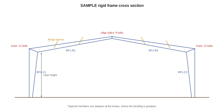
A tapered member is deeper at one end than the other. On the cross section, each piece's depth at both ends is shown, and the shipping marks on the steel tell the crew which end is which. A rafter half installed upside down or reversed may fit the bolt holes at one end and not at the other, and a crew that forces it wastes a day.
Connection details show the bolt grade and diameter, the number of bolts, the plate thicknesses and whether the bolts are to be snug-tight or pretensioned. In most metal building systems, the end-plate moment connections at the knees and ridge are made with high-strength bolts, and the manufacturer's notes say how they are to be tightened. Lesson 4 returns to this.
Sheeting, trim and the bill of material
The sheeting plans show the panel layout on each wall and roof: the panel type and gauge, the starting point and direction of lay, the panel lengths, and the location of every trim piece. Panel direction matters because most panels lap one way. The trim sheets show each trim piece in cross section with its part number, so the crew can identify the eave trim, rake trim, corner trim, base trim, jamb trim and head trim in the bundles.
The bills of material list every part by part mark, quantity, length and weight. The crew uses them to check the shipment when it arrives, to stage the pieces in the order they will be used, and to find which bundle holds a part. Fasteners are listed by type, size and quantity, usually with a small overage. A metal building can have tens of thousands of screws, and running out of one type on a Friday afternoon stops the job.
Corwin's crew checked every Brannock shipment against the list on the day it arrived, because the manufacturer's terms gave the builder only a short window to report shortages and damage. On July 6 they found one bundle of base angle short by four pieces and photographed a dented corner trim. Northfield shipped the replacements with the second load.
Revisions and changes
Every drawing has a revision block, and the erection set must match the building ordered. If the owner changes anything after the approval drawings, such as adding a door, moving an opening or changing a color, the manufacturer issues revised sheets. An erector who finds that the drawings and the steel do not match, or that a framed opening on the drawings does not match what the owner wants, stops and calls the builder. The manufacturer will usually not stand behind a building that was changed in the field without its approval.
On the Brannock job, Erin Brannock decided at the slab pour that she wanted a walk door on the back sidewall as well as the front. Corwin wrote the request on his daily report, Crossbeam's office ordered a field-installed framed opening kit from Northfield with an engineer's letter, and the door went in on August 11 with the other openings.
Common mistakes
MistakeBuilding from the approval drawings.
InsteadUse only the erection drawings that ship with the building, and check their revision.
MistakeReading a wall elevation from inside the building.
InsteadElevations are drawn as seen from outside; stand outside or reverse the drawing.
MistakeTreating anchor rods as locating pins.
InsteadThey carry uplift and shear; size, embedment and projection must be as drawn.
MistakeCutting or welding a frame member for a conduit or opening.
InsteadGet the manufacturer's written approval for any field modification.
MistakeLeaving the shipment check until the steel is needed.
InsteadCheck every load against the bill of material on the day it arrives.
Summary and key terms
- Approval drawings confirm the order; erection drawings ship with the steel and are the ones to build from.
- The cover sheet gives the building's size, design loads, codes, materials and general notes for the erector.
- Frame lines are numbered along the building and wall lines lettered across it.
- The anchor rod plan locates every rod and gives the column reactions, including outward thrust and uplift.
- Framing plans, elevations and cross sections show every piece, its part mark, its connections and its bracing.
- Sheeting and trim plans and the bills of material are used to stage, install and check the cladding and fasteners.
- Approval drawings
- The manufacturer's drawings sent to the builder and owner for confirmation before fabrication.
- Erection drawings
- The drawings that ship with the building and show how to assemble it.
- Anchor rod plan
- The drawing that locates and details every anchor rod and gives the column reactions.
- Column reaction
- The force a column puts on its foundation, vertical and horizontal, for each load case.
- Horizontal thrust
- The outward push at the base of a rigid frame column under roof load.
- Part mark
- The identifying number on each piece and on the drawings that tells where the piece goes.
Practice problems
Work each problem on paper first, then reveal the answer to check.
Which drawings should an erector build from?
Show answer
The erection drawings that ship with the building.
Why does a clear-span frame push outward at its base?
Show answer
Under roof load the rafters try to flatten, which pushes the column feet apart.
Five bays of 25 ft are shown. What should the building length be?
Show answer
5 × 25 = 125 ft.
What does a negative vertical reaction mean?
Show answer
Uplift: the column pulls up on the foundation.
From where are wall elevations drawn?
Show answer
As seen from outside the building.
Lesson quiz · 5 questions
Score 60% or more to complete this lesson.
Create a free account to save your progress, take quizzes and earn a certificate.