
IRW-220 · Lesson 8 of 12 · 21 min
Placing tendons and anchors
▶ Video coming soon A video version of this lesson is on the way.
In the second half of the November 7 session, Ruairi unrolled a Stratline shop drawing for one bay of Quarry Point Center on the bench and weighed its corners down with anchors. It was a plan of the deck covered in lines, each one a tendon or a group of tendons, with numbers along them every few meters. "Those numbers are the whole job," he said, tapping one. "Every one is a height. If the strand is at that height when the concrete goes in, the slab does what the engineer thinks it does. If it isn't, it doesn't."
Although Stratline's crew will place the tendons at Quarry Point, Crossbeam's rod gang will place the bars that hold them up, and the two crews will work on the same deck at the same time for months. Every rodbuster on a post-tensioned job needs to know how tendons are placed, how their profile is controlled and what damages them. This lesson covers the shop drawings, the placing sequence, tendon profiles and supports, anchors at the edges and at construction joints, and protecting the tendons until the pour.
Post-tensioning shop drawings
The post-tensioning supplier's shop drawings show, for each deck or pour:
- The tendon layout in plan, with every tendon or group identified, its number of strands and its length.
- The tendon profiles: the height of the center of gravity of the strand, called the CGS, at the high points over the supports, at the low points in the spans and at intermediate points, measured from the bottom of the slab.
- The support layout: where the support bars and chairs go and their heights.
- The stressing and fixed ends, intermediate anchors, and which edge or joint each tendon is stressed from.
- The anchor details, pocket formers, bursting steel references and edge distances.
- The calculated elongations and the stressing sequence, used in lesson 9.
The mild steel placing drawings and the post-tensioning shop drawings must agree, and before the first pour both crews walk through the first bay together with the drawings. At Quarry Point, Tobias and Ruairi have booked that walk for Tuesday, December 8, the second day of the job.
Placing sequence
The order of work on a post-tensioned deck is planned so that each crew can do its part without tearing out the other's. A typical sequence for a slab between beams is this, though the drawings and the agreed plan decide.
- Formwork, with edge forms drilled for the stressing tails and marked for the anchor positions.
- Bottom mild steel: the bottom bars of the slab, and the bottom bars and stirrups of the beams.
- Fixed-end anchors set at the edges where tendons are not stressed, often with the tendons arriving coiled with the fixed end already attached.
- Beam tendons, laid in the beam cages on their supports, then the slab tendons that cross the beams, in the order the drawing shows: banded or beam tendons first, distributed tendons over them.
- Support bars and chairs set to height under the tendons, tied to the tendons and to the supports.
- Stressing-end anchors nailed to the edge forms with pocket formers, and the tails passed through the forms.
- Top mild steel: bars over the beams and columns, at openings and edges, placed so that they do not push the tendons down.
- Bursting steel and other anchor-zone bars, sleeves and embeds.
- Inspection of both the mild steel and the tendons, and repair of any damage.
The worst conflicts come when one crew gets ahead of the other. If the top bars go in before the tendons are tied off, the tendons are pushed down. If the tendons go in before the bottom bars, the bars cannot be threaded under them. Tobias's plan for Quarry Point has the rod gang one bay ahead of Stratline's crew on the bottom steel and one bay behind on the top steel.
Tendon profiles
The profile is the shape the tendon follows along its length. In a continuous slab or beam, the tendon is high over each support, falls in a curve to a low point near midspan, and rises again. The shop drawing gives the CGS height at the controlling points, and the crew supports the tendon at those points and at enough points between them that it follows a smooth curve, usually close to a parabola.
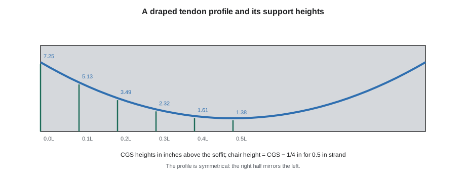
Heights on the shop drawing are usually to the CGS, the center of the strand. A chair holds the bottom of the strand, so the chair or support height is the CGS height minus half the strand diameter. Some suppliers show chair heights directly; the drawing's notes say which.
Worked problem
Support heights along a draped tendon
A 9 in slab spans 30 ft between supports. The tendon is a 0.5 in strand. Its CGS is 7-1/4 in above the soffit over the supports and 1-3/8 in at midspan, with a parabolic drape between. What are the CGS heights at the tenth points, and the chair heights to the underside of the strand?
Show solution
- For a parabola, the height at a point x along the span is y = 7.25 − (7.25 − 1.375) × 4x(L − x) ÷ L².
- At 0.1L: 4 × 0.1 × 0.9 = 0.36, so y = 7.25 − 5.875 × 0.36 = 5.135 in; chair = 5.135 − 0.25 ≈ 4-7/8 in.
- At 0.2L: 0.64, so y = 7.25 − 3.76 = 3.49 in; chair ≈ 3-1/4 in.
- At 0.3L: 0.84, so y = 7.25 − 4.935 = 2.315 in; chair ≈ 2-1/16 in.
- At 0.4L: 0.96, so y = 7.25 − 5.64 = 1.61 in; chair ≈ 1-3/8 in.
- At midspan: y = 1.375 in; chair ≈ 1-1/8 in. Over the support: y = 7.25 in; chair = 7 in.
Answer: The chairs step from 7 in at the support to about 1-1/8 in at midspan. Most of the drop happens in the first third of the span, which is why the supports near the high points must be set carefully: a mistake there changes the curve the most.
Supporting tendons
Tendons are held at their profile by support bars, short or continuous bars laid across the tendons' path on chairs of the right height, with each tendon tied down to them. In beams, the tendons sit on bars or chairs tied to the stirrups. Supports are spaced closely enough that the tendon does not sag between them under its own weight and the weight of workers stepping on it; suppliers commonly specify a maximum spacing of about 4 ft for monostrand tendons, and the shop drawing gives the actual spacing.
Tendons are tied to every support they cross, with wire or plastic ties that do not cut the sheathing. Chairs for tendons are plastic or coated, and in an encapsulated system no bare steel touches the sheathing.
Tendon height tolerances come from ACI 117 and the project specification: typically ±1/4 in for members up to 8 in deep, ±3/8 in for members over 8 in up to 2 ft, and ±1/2 in for deeper members, checked at the controlling points.
Horizontal position and sweeps
In plan, tendons run straight except where the drawing shows them sweeping around an opening, a column or another obstacle. A sweep must be a gentle curve, within the limits the supplier's notes give, not a sharp bend, because a sharp bend makes the tendon push sideways on the concrete when stressed and can break out the slab edge or an opening. Tendons are never moved sideways to clear a sleeve or conduit without checking the drawing, and where two crews' items clash, the sleeve or conduit usually moves, not the tendon. A tendon that must move more than the drawing allows is an RFI.
Anchors at edges and joints
Anchors are where the tendon force enters the concrete, and they need care.
- Each anchor is set square to the tendon, with the tendon straight for a set length behind it, so that the strand does not kink where it enters the anchor. The supplier's notes give the straight length.
- Stressing anchors are nailed tight to the edge form, with the pocket former between the anchor and the form, so that concrete cannot get behind the anchor or into the wedge cavity.
- The strand tail through the edge form is left long enough for the jack to grip, usually about 2 ft or as the supplier says.
- Bursting steel goes behind every anchor as the drawings show, and the anchors keep their specified distance from slab edges, corners and each other.
- Fixed-end anchors are set at their edge with the bursting steel and tied so that they cannot move.
- Intermediate anchors at construction joints are fixed to the bulkhead so that the second pour's tendon can be stressed from the joint.
Concrete behind an anchor must be fully compacted. Honeycomb or voids behind an anchor can let it punch through the concrete when the tendon is stressed, so the concrete crew vibrates the anchor zones carefully, and the rod gang leaves room for the vibrator between the bursting bars.
Protecting tendons until the pour
Most damage to tendons happens on the deck between placing and pouring. Sheathing is cut by sharp tools, burned by welding sparks or torches, crushed under equipment and torn when workers drag bars over it. A small tear lets cement paste in against the strand and grease out, and on an encapsulated system it breaks the corrosion protection.
- Walk on the support bars or walkways, not on the tendons.
- Keep welding and cutting away from tendons; where welding is unavoidable nearby, the supplier's procedure and fire blankets are used, and the strand is never used as a ground.
- Do not set bundles, tools or concrete buckets on tendons.
- Report damage to the post-tensioning crew; small tears are repaired with the supplier's repair tape, overlapping the damaged area as its procedure says, and larger damage may mean the tendon is replaced.
- Keep the stressing tails clean and protected, because damaged strand at the tail cannot be gripped by the jack.
Placing banded and distributed tendons
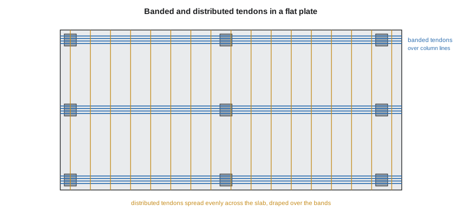
In a two-way flat plate, the banded tendons go in first, laid in a narrow band along each column line at their profile, with the high points over the columns and low points at midspan. The distributed tendons in the other direction go in second and drape over the banded ones. At every crossing, the two must work: the distributed tendon cannot pass under a banded tendon at a point where its profile says it should be above. The shop drawing shows which goes over which, and the supports are set so that both tendons are at their correct heights where they cross. Laying tendons in the wrong order often means lifting a whole band to slide the other tendons under it, which damages the sheathing and wastes a day.
In beam-and-slab parking structures, the beam tendons go into the beam cages first, often with several tendons in a bundle at the bottom of the beam at midspan and rising to near the top over the columns. Bundled beam tendons are held in a tight group by ties and supported on bars tied to the stirrups, and the stirrups must have room around them for the tendons at every point along the beam. The slab tendons are then laid across the beams, rising over each beam and dropping into the slab spans between them.
Checking the tendons before calling inspection
Before Stratline calls for inspection, its crew walks every tendon from end to end with the shop drawing. They check that every tendon is present and in the right place, measure the heights at every high point and low point, and check the support spacing and ties. They look along each tendon for kinks and wobble, check the sweeps around openings, and look at every anchor: square to the tendon, nailed tight, with its pocket former and tail in place. Damaged sheathing is repaired as they go. Ruairi signs a tendon checklist for each pour, and the rod gang's foreperson signs the mild steel checklist, and only then is the inspector called.
Tobias and Ruairi have agreed that at Quarry Point the two crews will make that walk together for the first three pours, so that each sees what the other checks.
Rod gang members who see a tendon that looks wrong, such as one that has slipped off its support, a kink, a crushed sheath or an anchor knocked crooked, tell the post-tensioning crew straight away rather than fixing it themselves.
Common mistakes
MistakeMeasuring tendon heights to the top of the strand.
InsteadProfile heights are usually to the CGS; chair heights are the CGS minus half the strand diameter.
MistakePutting the top bars in before the tendons are tied off.
InsteadPlace top steel after the tendons are supported and tied, without pushing them down.
MistakeMoving a tendon sideways to clear a conduit.
InsteadMove the conduit or ask; tendons sweep only as the drawing allows.
MistakeLeaving a gap between the stressing anchor and the edge form.
InsteadNail the anchor tight with its pocket former.
MistakeWalking along tendons on the deck.
InsteadWalk on support bars or walkways, and report any sheathing damage.
Summary and key terms
- The PT shop drawings show layout, profiles, supports, ends, anchors, elongations and the stressing sequence.
- Placing is a planned sequence: bottom steel, fixed ends, tendons, supports, stressing anchors, top steel, then inspection.
- Profiles are given as CGS heights at controlling points; chair heights are the CGS minus half the strand diameter.
- Supports are spaced as the supplier specifies, often about 4 ft, and heights are held to ACI 117 tolerances.
- Sweeps in plan are gentle and only as shown; obstacles usually move instead of tendons.
- Anchors are square, straight behind, tight to the form, with bursting steel and well-compacted concrete.
- Sheathing damage is reported and repaired before the pour.
- CGS
- The center of gravity of the strand, the point to which tendon heights are usually given.
- Profile
- The vertical shape of a tendon along its length.
- Support bar
- A bar on chairs, laid across tendons to hold them at their profile.
- Sweep
- A gentle horizontal curve in a tendon around an obstacle.
- Stressing tail
- The length of strand left through the edge form for the jack to grip.
- Intermediate anchor
- An anchor at a construction joint, from which the next pour's tendon is stressed.
- Anchor zone
- The concrete behind an anchor, where the tendon force spreads out.
Practice problems
Work each problem on paper first, then reveal the answer to check.
A tendon's CGS is 6 in at a point, and the strand is 0.5 in. What chair height is needed?
Show answer
6 − 0.25 = 5-3/4 in.
What is the midspan factor 4x(L − x) ÷ L² at x = 0.5L?
Show answer
4 × 0.5 × 0.5 = 1.0.
Which goes in first, the top bars or the tendons?
Show answer
The tendons, supported and tied; the top bars after.
Why must an anchor be nailed tight to the form?
Show answer
So that concrete cannot get behind it or into the wedge cavity.
A tendon clashes with an electrical conduit. What usually moves?
Show answer
The conduit, unless the drawing allows a sweep.
Lesson quiz · 5 questions
Score 60% or more to complete this lesson.
Create a free account to save your progress, take quizzes and earn a certificate.