
IRW-220 · Lesson 5 of 12 · 21 min
Mechanical splices and couplers
▶ Video coming soon A video version of this lesson is on the way.
IRW-130 ended its story of the Harrow Square parkade with RFI 14. In June 2026, the gang found that the laps shown for the heavy bars in the transfer slab would not fit: with four layers of large bars crossing the column bands, there was no room for the extra bar length of a lap anywhere near the columns. Fenwick Structural answered on June 24 with a detail that replaced the laps with couplers, and the couplers arrived on June 29. At the Saturday session on October 31, Tobias brought one of the spare couplers, a heavy steel sleeve with threads inside, and passed it round with two short bar ends threaded to fit. "This little thing," he said, "saved us about three days and half a metric ton of steel. And it cost me two evenings learning how to put it on right."
A mechanical splice, usually called a coupler, joins two bars end to end with a device instead of overlapping them in a lap. This lesson covers why couplers are used, the main types, the rules for their strength, how they are installed and checked, and headed bars, which use similar hardware.
Why use couplers
Laps are cheap and simple, so most splices are laps. Couplers are used where a lap will not work or will not do the job.
- Congestion. A lap doubles the steel at the splice. In heavily reinforced columns, beams and transfer slabs, there may be no room for the second bar.
- Large bars. Laps of the largest bars are very long, and some codes do not allow laps of the largest sizes at all.
- Construction joints and staged work. A coupler cast into the first pour leaves a flush end with no bar sticking out, ready for the next bar to screw in. This is used at slab-wall joints, at diaphragm walls and where projecting dowels would be in the way or a hazard.
- Strength. Where the design needs the splice to be as strong as the bar itself, as in some seismic and bridge details, a suitable coupler can provide it.
- Savings in steel. On long runs of large bars, the steel in the laps adds up, and couplers can cost less overall.
Worked problem
The steel in the laps
At Harrow Square, 40 bottom bars of #11 across one column band were to be lapped, with a lap of 76 in shown on the original detail. How much steel would the laps have used, and what did the couplers save in length?
Show solution
- Extra length = 40 × 76 = 3,040 in = 253.3 ft.
- Weight = 253.3 × 5.313 = 1,346 lb.
Answer: About 253 ft of bar and 1,346 lb of steel in one band, more than half a ton. More important, the couplers removed the second bar from the most congested part of the slab, so the concrete could flow.
Types of couplers
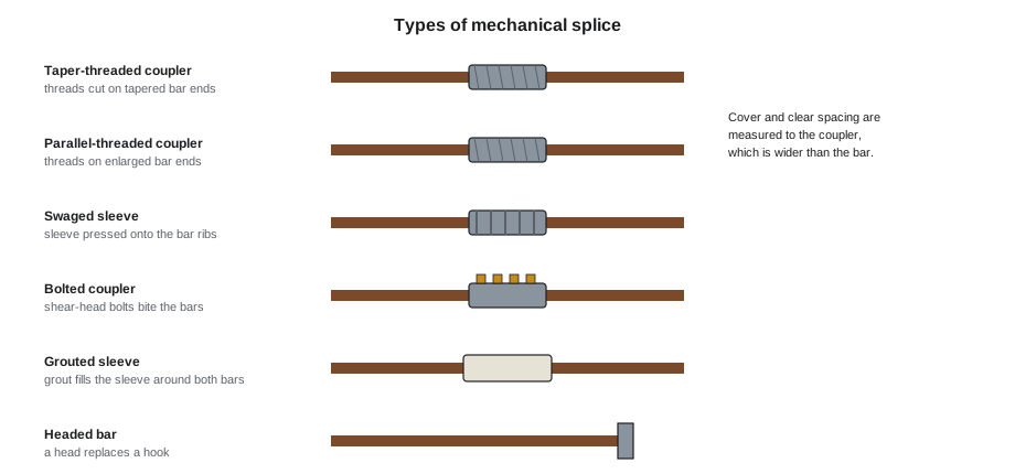
- Threaded couplers. The bar ends are threaded in the fabricator's shop, and a sleeve with matching internal threads joins them. Taper threads seat quickly with a few turns and are tightened to a set torque. Parallel threads are usually cut on bar ends that have been enlarged by forging or cold-working first, so that cutting the threads does not reduce the bar's strength. Threaded couplers come in standard, position and transition versions: position couplers allow joining a bar that cannot be rotated, and transition couplers join two different bar sizes.
- Swaged or cold-pressed sleeves. A steel sleeve is slipped over both bar ends and pressed onto the bar ribs with a hydraulic press on site, deforming the sleeve into the ribs.
- Bolted or shear-screw couplers. A sleeve with a row of bolts is slipped over both bars, and the bolts are tightened until their heads shear off at a designed torque, biting into the bars. They need no bar-end preparation, which makes them useful for repairs and for bars already cast in.
- Grouted sleeves. One bar is cast into a precast member with a sleeve around its end; on site, the bar from the next member is inserted into the sleeve and the sleeve is filled with high-strength grout. They are common for precast column and wall connections.
- Other types include sleeves filled with molten metal, wedge-locking sleeves and compression-only end-bearing sleeves. Each is a proprietary system with its own approvals.
Every coupler system is proprietary. Its manufacturer publishes the installation instructions, the tools, the bar preparation and the inspection checks, and those instructions are part of the job's requirements as much as the drawings.
How strong must a coupler be
ACI 318 sets two levels. A Type 1 mechanical splice must develop at least 125 in 100 of the bar's specified yield strength in tension or compression. A Type 2 splice must meet the Type 1 requirement and also develop the bar's specified tensile strength. In the special seismic frames and walls of ACI 318 Chapter 18, Type 1 splices may not be used near the beam and column faces where yielding is expected, while Type 2 splices have fewer location limits. Coupler systems are tested to ASTM A1034 and are often evaluated under the ICC-ES acceptance criteria AC133, and state transportation departments, including ODOT, keep lists of accepted systems for bridges.
For the rodbuster this means three things. First, use only the coupler system named on the drawings or the approved submittal, never a substitute from the truck. Second, keep the paperwork: the submittal, the test reports and the mill certificates for the bars it joins. Third, install every coupler exactly as its instructions say, because the tested strength depends on it.
Installing threaded couplers
On Harrow Square, Northbar threaded the bar ends in its shop and shipped them with plastic caps on the threads, and the couplers were screwed onto one bar of each pair before delivery. Tobias's gang followed the manufacturer's sheet, which listed these steps.
- Check the bar ends. The threads must be clean, undamaged and the right size. Caps stay on until the bar is joined. A bar with damaged threads is set aside and replaced, not forced.
- Check the coupler. Right size and type, threads clean, no cracks.
- Screw in the bars until the ends meet in the middle of the coupler, or until the engagement marks painted on the bars line up with the coupler ends, as the system requires.
- Tighten to the specified torque with a calibrated torque wrench, for systems that require torque, or by hand and wrench to remove play for systems that do not.
- Mark each completed coupler with paint so the inspector can see it is done.
- Record the count and locations for the inspection.
Thread engagement is the critical check. If a bar is only partly screwed in, the coupler may hold during placing and pull apart under load. The engagement marks, or a gauge from the supplier, show whether each bar is fully home. On Harrow Square, Leona Fitzgerald of Fenwick Structural reviewed the first ten installations herself on June 30 before the gang went on.
Staggering and placing couplers
Couplers are bulkier than bars. A coupler for a large bar may be about twice the bar diameter across, so cover and clear spacing are measured to the coupler, not to the bar. Where many bars are spliced in one place, the couplers are staggered along the bars as the drawings show, so that they are not all in one line, which would both weaken a section and block the concrete. Couplers in adjacent bars at Harrow Square were staggered by about 30 in, as Fenwick's detail required.
Couplers cast flush into a first pour, for a later bar, are fixed to the formwork with nail plates or bolts so that they stay in position and concrete does not get into the threads. When the form is stripped, the caps come off, the threads are checked, and the next bar screws in. A bar end left projecting from the first pour, with a coupler waiting on it, is capped against impalement like any dowel.
Headed bars
Headed bars, mentioned in lesson 1, use a head forged onto the bar end or threaded or friction-welded onto it. The head anchors the bar by bearing on the concrete, so it can replace a hook in a shorter space.
Headed bars and their heads are made to ASTM A970, and ACI 318 sets how they are used and developed.
Heads must be placed exactly where shown, usually just inside the far reinforcement, with the bearing face of the head toward the load. In the column-to-slab joints of a parking structure, headed shear studs on rails, called shear stud rails, are also used to strengthen the slab around columns against punching shear, and they have to be placed with their rails on the bottom and studs at the spacing shown, often between the tendons and bars of a post-tensioned slab.
Inspecting couplers
The inspector checks couplers against the drawings and the manufacturer's instructions. On most jobs this means checking the system and size, the locations and stagger, the engagement and tightness of each coupler, the paint marks, the cover to the coupler, and the paperwork. On some jobs the specification requires sample splices to be made with the same bars, tools and crew, and tested in a laboratory before production starts, or a set number of production splices to be cut out and tested.
Ordering and storing couplers
Couplers are ordered from the approved submittal by type and size, and the bars that go into them are prepared by the fabricator to that system: threaded, forged or cut square as the system requires. On Harrow Square, Ashok Menon of Northbar issued a coupler schedule along with the revised placing drawing, listing every coupler by bar mark, size, type and location, and Northbar shipped the bars and couplers together, sorted by area. Spare couplers and spare threaded bar ends came with each delivery, so that a damaged thread could be replaced without waiting.
Couplers and threaded bar ends are stored off the ground, under cover, with their thread caps on. Threads damaged by dragging, dropping or concrete splatter cannot be repaired on site by filing or forcing, because a poorly cut thread changes the splice's strength. A bar with a damaged thread is set aside, tagged and replaced.
Torque wrenches
Systems that are tightened to a set torque need a calibrated torque wrench, and the specification usually requires a calibration certificate for each wrench. The wrench is set to the value on the coupler maker's sheet, which depends on the bar size, and the bar is turned until the wrench clicks or signals. Over-tightening can damage threads; under-tightening leaves play in the joint. The person tightening marks the coupler with paint as soon as it reaches torque, so that nobody has to guess which ones are done. On Harrow Square, each pair of rodbusters on coupler work carried its own wrench, and Renata checked the wrenches against a test fixture each morning.
Couplers on post-tensioned jobs
On post-tensioned jobs, couplers are often used at construction joints in walls and beams, where projecting dowels would get in the way of the edge forms and stressing pockets, or would be an impalement hazard on a busy deck edge. They are also used to join the heavy bars in transfer girders and at the column-to-beam joints of parking structures, where tendon bundles leave little room for laps. Couplers must not be placed where they would clash with a tendon, an anchor or its bursting steel, and their positions are checked on the overlay of the mild steel and post-tensioning drawings described in lesson 1.
Tendons themselves can also be joined. Post-tensioning suppliers make tendon couplers that join one tendon to the next at a construction joint, and bonded systems have coupler heads that let a tendon be extended in a later pour. These are part of the post-tensioning system, installed and stressed only by the supplier's crew, and the rod gang leaves the space their drawings show around them.
When a coupler is missing
If a coupler is missing, cracked or the wrong size when the bars arrive, the gang does not substitute a lap or a different coupler without the engineer's approval. A lap may not fit, and a different system may not have the tested strength. On Harrow Square, one coupler was dropped into the excavation and cracked on June 30; the gang tagged it, set it aside and fitted a spare from the same shipment. Every spare used was noted in the coupler log so that the count matched the schedule.
Common mistakes
MistakeUsing a different coupler system from the one approved.
InsteadUse only the system on the drawings or the approved submittal.
MistakeRemoving thread caps when the bars are unloaded.
InsteadLeave caps on until the bar is joined.
MistakeLeaving a bar partly screwed in.
InsteadCheck engagement marks or the gauge on every coupler.
MistakeMeasuring cover to the bar instead of to the coupler.
InsteadCover and clear spacing are measured to the coupler.
MistakeLining up all the couplers in one section.
InsteadStagger them as the drawings show.
Summary and key terms
- Couplers replace laps where congestion, bar size, staged pours or strength make laps unsuitable.
- Main types are threaded, swaged, bolted and grouted sleeve couplers, each proprietary with its own instructions.
- ACI 318 Type 1 splices develop 125 in 100 of yield; Type 2 also develop the specified tensile strength; systems are tested to ASTM A1034.
- Installation depends on clean threads, full engagement, the right torque and marking each coupler.
- Cover and spacing are measured to the coupler, and couplers are staggered.
- Headed bars and shear stud rails anchor steel in a short space and must be placed exactly.
- Coupler
- A device that joins two bars end to end.
- Mechanical splice
- A splice made with a coupler instead of a lap.
- Position coupler
- A threaded coupler that joins bars when neither can be rotated.
- Transition coupler
- A coupler that joins two bars of different sizes.
- Grouted sleeve
- A sleeve filled with grout to join a projecting bar to a cast-in bar.
- Engagement mark
- A paint mark showing how far a bar must go into a coupler.
- Shear stud rail
- A rail of headed studs placed around columns to resist punching shear.
Practice problems
Work each problem on paper first, then reveal the answer to check.
Thirty #10 bars would need laps of 60 in. How much bar do the laps add?
Show answer
30 × 5 = 150 ft, which is 150 × 4.303 = 645.5 lb.
Cover to a #11 bar is 2 in. A coupler on it is about 2-3/4 in across. Is the cover to the coupler still 2 in?
Show answer
No; the coupler is wider than the bar, so cover to its surface is less. Cover is checked to the coupler.
What standard tests mechanical splices?
Show answer
ASTM A1034.
Which coupler needs no bar-end preparation?
Show answer
A bolted or shear-screw coupler.
What shows that a threaded bar is fully screwed in?
Show answer
The engagement marks or the supplier's gauge.
Lesson quiz · 5 questions
Score 60% or more to complete this lesson.
Create a free account to save your progress, take quizzes and earn a certificate.