
IRW-130 · Lesson 10 of 12 · 24 min
Welded wire reinforcement
▶ Video coming soon A video version of this lesson is on the way.
Before the concrete goes on the Ashcroft floors, the rod gang has one more job there: laying welded wire reinforcement on the composite deck that Carla's gang finished on November 13. The sheets are due on site on Monday, November 16, and Tobias plans to have them placed, lapped, chaired and tied by Friday, November 20, ahead of the pours planned for the last week of the month. At the November 2 rod school night he brought a sheet of the mesh into the shop, stood it against the wall and asked the apprentices to read its tag. "It is the easiest steel you will ever place," he said, "and the one people get wrong most often, because they think it is easy."
This lesson covers welded wire reinforcement: what it is, how it is designated, where it is used, how it is lapped and supported, and the hazards of handling it.
What welded wire reinforcement is
Welded wire reinforcement, often shortened to WWR and also called welded wire fabric or mesh, is a grid of steel wires welded together at every crossing in the factory. The wires may be plain, smooth wire, or deformed, with indentations or ribs like small rebar. Because every crossing is welded, a sheet holds its spacing perfectly without ties, places quickly and anchors into the concrete through its cross wires as well as through bond.
WWR is used for temperature and shrinkage steel and light reinforcing in slabs on grade, slabs on composite metal deck, toppings, walls of tilt-up and precast panels, pipes and many precast products. Heavier, engineered sheets made to order, sometimes called structural WWR, replace bar mats in slabs, walls and box culverts, with the advantage that one sheet replaces hundreds of tied crossings.
In the United States, WWR is made to ASTM A1064, the standard for plain and deformed wire and welded wire reinforcement. The wire is cold drawn and has a higher yield strength than ordinary rebar.
Reading the designation
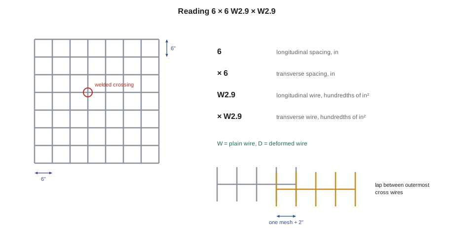
A WWR designation gives the spacing of the wires in each direction, then the size of the wires in each direction. The wire size is the cross-sectional area of the wire, and a letter in front tells whether the wire is plain or deformed.
Designations give spacings in inches and wire areas in hundredths of a square inch, with W for plain wire and D for deformed wire. A sheet designated 6 × 6 W2.9 × W2.9 has wires 6 in apart in both directions, each plain wire with an area of 0.029 in². The first spacing and the first wire size are for the longitudinal wires, which run the length of the sheet or roll; the second pair is for the transverse wires. Older drawings may show the same sheet in the gauge style, 6 × 6 6/6, and metric drawings show it as 152 × 152 MW18.7 × MW18.7.
| Designation | Metric equivalent | Wire spacing | Wire area each way |
|---|---|---|---|
| 6 × 6 W1.4 × W1.4 | 152 × 152 MW9.1 × MW9.1 | 6 in | 0.014 in² |
| 6 × 6 W2.9 × W2.9 | 152 × 152 MW18.7 × MW18.7 | 6 in | 0.029 in² |
| 4 × 4 W2.1 × W2.1 | 102 × 102 MW13.3 × MW13.3 | 4 in | 0.021 in² |
| 4 × 4 W4.0 × W4.0 | 102 × 102 MW25.8 × MW25.8 | 4 in | 0.040 in² |
Worked problem
How much steel is in a sheet
For 6 × 6 W2.9 × W2.9, what steel area per foot of width does the mesh give in each direction, and what is its approximate weight per square foot? (A steel wire with an area of 1 in² weighs about 3.4 lb per foot.)
Show solution
- Wires per foot = 12 ÷ 6 = 2.
- Area per foot = 2 × 0.029 = 0.058 in² per foot in each direction.
- Weight of one wire = 0.029 × 3.4 ≈ 0.099 lb/ft.
- Weight per ft² = 2 directions × 2 wires × 0.099 ≈ 0.39 lb/ft².
Answer: About 0.058 in² per foot each way, roughly the area of one #3 bar at 22 in, and about 0.39 lb/ft². That is why stock mesh is used for crack control rather than for main strength.
Sheets and rolls
Light WWR is sold in rolls as well as flat sheets. Rolls are cheaper to ship but have a memory: unrolled mesh wants to curl back up, and it is very hard to get it flat and at the right height. Most specifications for structural use, and Crossbeam's own practice, call for flat sheets. Where rolls must be used, they are unrolled, flipped over, walked flat and held down at the ends before they are cut.
Cutting WWR is done with bolt cutters or a cut-off saw, cutting wires between the crossings. A cut sheet edge is a row of sharp wire ends, and it is handled with gloves, sleeves and eye protection.
Where the mesh goes
The most common mistake with WWR is not in the mesh but in its height. Mesh lying on the ground or on the deck is in the wrong place: it is at the bottom of the slab, where it does almost nothing to control the shrinkage cracks that open at the top surface. The drawings show the position, usually at a set distance below the top surface or at mid-depth of the slab, and the mesh must be held there on supports.
An old habit, still seen on small jobs, is to lay mesh on the ground and pull it up into the concrete with a hook during the pour. Studies and inspectors have shown for decades that pulled-up mesh ends up anywhere from the bottom to the top of the slab, and usually at the bottom. Hooking up mesh is not an acceptable substitute for supporting it, and specifications commonly say so.
On the Ashcroft composite deck, the drawings show the mesh with 1 in cover below the top surface. Tobias's gang will set it on continuous wire supports that sit on the high flutes of the deck, at the spacing the specification gives, and tie the sheets to the supports and to each other at laps. Shear studs, welded through the deck by Nate's crew, stand up through the mesh; the sheets are cut and fitted around the studs and the column openings, not bent down over them.
Lapping sheets
Sheets are lapped where they meet, so that the mesh is continuous across the slab. Because WWR anchors through its welded cross wires, laps are measured between the outermost cross wires of the two sheets. For plain wire mesh, a common requirement is that the outermost cross wires of the two sheets overlap by at least one full mesh spacing plus 2 in, but the specification and the drawings set the lap for each job, and heavier or deformed sheets may need longer laps.
Laps are tied together, and the sheets are laid so that the laps in adjacent rows are staggered. Lapping more than two layers at a corner where four sheets meet makes a thick stack that loses cover; the corners of the sheets are cut back so that no more than two layers overlap at any point.
Worked problem
How many sheets for a floor
An Ashcroft floor deck is about 100 ft by 160 ft. Sheets are 8 ft by 20 ft, and each lap uses 8 in of sheet in each direction (one 6 in mesh plus 2 in). How many sheets are needed, and how many with an allowance of 5 in 100 for cutting around openings and edges?
Show solution
- Effective size of each sheet = (8 − 0.67) × (20 − 0.67) ≈ 7.33 × 19.33 ≈ 141.8 ft².
- Floor area = 100 × 160 = 16,000 ft².
- Sheets = 16,000 ÷ 141.8 ≈ 112.9, so 113.
- With the allowance: 16,000 × 1.05 ÷ 141.8 ≈ 118.5, so 119.
Answer: About 119 sheets per floor. Ordering by simple area, 16,000 ÷ 160 = 100 sheets, would leave the gang 13 sheets short before a single cut.
Handling and safety
WWR is light per square meter but awkward and springy in bulk. A sheet is large, catches the wind like a sail and has sharp ends on every edge.
- Bundles of sheets are unloaded and lifted with the crane, rigged as the supplier and the lift plan direct; sheets are not slid off the truck by hand.
- On a deck or roof, sheets are not left loose where wind can catch them; bundles are banded and secured until they are placed, and placed sheets are tied down.
- Rolls spring open when their bands are cut. OSHA 1926.703(d) requires employers to take measures to prevent unrolling of wire mesh; before cutting the bands, the roll is turned so that it unrolls away from the worker, and the free end is held down.
- Gloves, long sleeves and eye protection are worn when handling, cutting and placing mesh; cut ends are a common cause of hand and face injuries.
- On composite deck, the edges of the floor and the openings are fall hazards; the guardrails and covers from IRW-110 stay in place, and sheets are not laid over unprotected openings, where they can hide a hole.
Mesh and bars together
Many slabs have both: bars in the main directions or over supports, and mesh for crack control near the top. Others use mesh as the main steel in a thin topping. The drawings show which layer is which, and the order and supports are worked out from the section, as in lesson 5. Where the drawings show additional bars over beams on a composite deck, they go over the mesh or under it exactly as the section shows, and the cover is checked to the outermost steel.
Structural welded wire
Heavier welded wire, made to order, is used as main reinforcement in slabs, walls, precast panels, pipes and box culverts. A single engineered sheet can replace a whole mat of tied bars, with every crossing already welded and every bar at its exact spacing. The sheets are designed for the job, with wire sizes and spacings chosen by the engineer, and are shown on the placing drawings like bar mats, each with a mark. They are heavy, often lifted with a spreader at marked pick points, and they are lapped and supported exactly as the drawings show. Because the wires are cold drawn and welded, structural sheets must not be bent on site unless the maker and the engineer allow it.
Deformed wire reinforcement, with D or MD designations, bonds better than plain wire and is used where the mesh is doing structural work. A placer who sees D wire on a drawing knows the mesh is not just for crack control, and that its position, laps and cover matter as much as those of any bar.
Worked problem
Comparing mesh to bars
A slab drawing calls for 4 × 4 W4.0 × W4.0. What steel area per foot does it give in each direction, and roughly what spacing of #3 bars (0.11 in²) gives the same?
Show solution
- Wires per foot = 12 ÷ 4 = 3.
- Area = 3 × 0.040 = 0.12 in² per foot.
- #3 spacing = 0.11 ÷ 0.12 × 12 ≈ 11 in.
Answer: About 0.12 in² per foot, about the same as #3 at roughly 11 in. The mesh puts that steel in many small wires close together, which controls cracks better than a few bars far apart.
Whether mesh or bars, the steel must end up where the drawing shows it. Tobias's last words on the subject at rod school were the same as his first: "Easy steel is still steel."
On the Ashcroft deck, Tobias has planned the sheet layout on a copy of the deck drawing, starting each row from the same edge, staggering the end laps by half a sheet from row to row and marking the cuts around the columns and the openings. The layout tells the crane operator the order the bundles are needed in and tells the gang where every sheet goes before the first one is lifted.
Common mistakes
MistakeLaying mesh on the ground or deck and pulling it up during the pour.
InsteadSupport the mesh at the height on the drawings.
MistakeMeasuring laps from the cut ends of the sheets.
InsteadMeasure laps between the outermost cross wires of each sheet.
MistakeStacking four layers of mesh at a sheet corner.
InsteadCut back the corners so no more than two layers overlap.
MistakeCutting the bands of a roll with the roll facing you.
InsteadTurn the roll to unroll away from you and hold the free end down.
MistakeLeaving loose sheets on a deck in the wind.
InsteadKeep bundles banded and secured, and tie placed sheets down.
Summary and key terms
- WWR is a grid of plain or deformed wires welded at every crossing, used for crack control and as engineered reinforcement.
- Designations give spacing in inches and wire area in hundredths of a square inch: 6 × 6 W2.9 × W2.9.
- Stock mesh gives a small area of steel per width; it is for crack control.
- Mesh must be supported at the height shown; pulled-up mesh ends up at the bottom.
- Laps are measured between the outermost cross wires; a common rule is one mesh plus 2 in, but the specification governs.
- Prefer flat sheets; control rolls when the bands are cut; secure sheets against wind; protect hands and eyes.
- Welded wire reinforcement
- A factory-made grid of steel wires welded at every crossing.
- Longitudinal wire
- A wire running the length of a sheet or roll.
- Transverse wire
- A wire running across the width of a sheet or roll.
- Plain wire
- Smooth wire, shown by W or MW in a designation.
- Deformed wire
- Wire with indentations or ribs, shown by D or MD in a designation.
- Structural WWR
- Heavy welded wire sheets made to order as main reinforcement.
- Outermost cross wire
- The last cross wire at the edge of a sheet, from which laps are measured.
Practice problems
Work each problem on paper first, then reveal the answer to check.
What does 4 × 4 W4.0 × W4.0 mean?
Show answer
Plain wires 4 in apart each way, each with an area of 0.040 in².
A slab is 60 ft by 80 ft; sheets cover 141.8 ft² each after laps. How many sheets?
Show answer
4,800 ÷ 141.8 ≈ 33.9, so 34 sheets before any allowance.
Where is the lap measured between two sheets?
Show answer
Between the outermost cross wires of each sheet.
Is hooking mesh up during the pour acceptable?
Show answer
No; mesh must be supported at the specified height.
What does D mean in D4.0?
Show answer
Deformed wire with an area of 0.040 in².
Lesson quiz · 5 questions
Score 60% or more to complete this lesson.
Create a free account to save your progress, take quizzes and earn a certificate.