
HSE-311 · Lesson 8 of 12 · 25 min
Safeguards and safety instrumented systems
Lesson 7 showed how LOPA credits independent protection layers. This lesson looks at the safeguards themselves: how they are chosen, what makes them reliable, and how they fail in practice. It covers the hierarchy of safeguards, pressure relief, safety instrumented systems under IEC 61511, and the management of bypasses and impairments. Detailed SIL verification mathematics for machinery and general electrical, electronic and programmable systems under IEC 61508 and IEC 62061 is covered in ROB-450; here we focus on the process industry standard IEC 61511 and on what a process safety practitioner needs to know to ask the right questions.
A hierarchy of safeguards
Not all safeguards are equal. The most robust remove or reduce the hazard; the weakest depend on a person noticing and acting in time. The CCPS hierarchy, which echoes the general hierarchy of controls, ranks safeguards from inherent to procedural.
| Category | Description | Example for reactor R-101 |
|---|---|---|
| Inherent | Eliminates or reduces the hazard itself | Semi-batch feed so that only a small amount of unreacted acid chloride is present at any time |
| Passive | Works without any action or energy | Vessel designed to contain the maximum runaway pressure; dike around the toluene tank |
| Active engineered | Detects a condition and acts automatically | Independent high-temperature trip that closes the feed valve; rupture disc |
| Procedural | Depends on people following instructions | Operator checks cooling flow before starting the feed; responds to alarms |
In practice a scenario is protected by a mix of these. The aim is to push the design as far up the hierarchy as reasonably practicable, and to recognize that procedural safeguards need the support of good alarm design, training and workload management (Lesson 11).
Pressure relief
Pressure relief devices protect equipment from overpressure by opening and discharging fluid when the pressure reaches a set value. Relief valves reclose when the pressure falls; rupture discs burst and stay open. A relief device is a last line of defense against vessel rupture, but it only works if it is sized for the right scenario, installed correctly, maintained, and discharges somewhere safe.
Relief design starts by listing every credible cause of overpressure, such as a blocked outlet, external fire, control valve failure, loss of cooling or a runaway reaction, and then finding the relief rate needed for the worst one. For simple vapor cases, the required relief flow can be estimated from a mass or energy balance: the device must remove material at least as fast as it is generated. Runaway reactions often produce two-phase flow of liquid and vapor, which needs a much larger relief area than vapor alone; methods developed by the Design Institute for Emergency Relief Systems (DIERS) are used for these cases.
# Simple relief load estimate for an external fire on a vessel of boiling liquid (illustrative).
# Heat input from fire Q (kW) boils off liquid at rate m = Q / latent heat.
wetted_area = 25.0        # m^2 of vessel wall in contact with liquid
fire_flux = 30.0          # kW/m^2 absorbed (illustrative value for an unprotected vessel)
latent_heat = 360.0       # kJ/kg, toluene near its boiling point
Q = wetted_area * fire_flux
m = Q / latent_heat
print(f"Heat input from fire: {Q:.0f} kW")
print(f"Boil-off rate:        {m:.2f} kg/s = {m * 3600:.0f} kg/h")

# A runaway can be far larger: heat release from reaction at a rate of 150 W/kg of batch
batch_mass = 8000.0       # kg
runaway_rate = 0.15       # kW/kg at the start of relief (illustrative)
Q_rx = batch_mass * runaway_rate
print(f"Runaway heat release: {Q_rx:.0f} kW -> {Q_rx / latent_heat:.2f} kg/s boil-off")
print(f"Ratio runaway to fire case: {Q_rx / Q:.1f}")Heat input from fire: 750 kW Boil-off rate: 2.08 kg/s = 7500 kg/h Runaway heat release: 1200 kW -> 3.33 kg/s boil-off Ratio runaway to fire case: 1.6
The numbers are illustrative, but the lesson is real: the runaway case can exceed the fire case, and if the relief device was sized only for fire it may be far too small. Detailed sizing uses methods in standards such as API 520 and API 521 in the oil and gas sector and DIERS methods for reactive systems; this course does not cover those calculations. What matters here is that every relief device has a documented design basis that is checked whenever the process changes (Lesson 9).
| Relief failure mode | How it happens | Control |
|---|---|---|
| Device sized for the wrong case | Runaway or two-phase flow not considered | Relief design basis reviewed in PHA and MOC |
| Inlet or outlet blocked | Isolation valve left closed, plugged with polymer or ice | Car-sealed open valves, inspection, heat tracing |
| Set pressure wrong | Wrong spring fitted after maintenance | Tagging, records and testing |
| Discharge to an unsafe place | Vents to atmosphere near people or ignition | Route to flare, scrubber or catch tank |
| Rupture disc damaged | Fatigue, corrosion, installed upside down | Inspection and correct installation procedures |
Texas City in 2005 is the classic example of a relief system discharging to an unsafe place: the blowdown drum vented hydrocarbon liquid and vapor directly to atmosphere, where it ignited. In the United States, OSHA PSM requires relief system design and design basis to be part of process safety information, and most states adopt the ASME Boiler and Pressure Vessel Code and National Board Inspection Code for installation and repair of relief devices.
Safety instrumented systems
A safety instrumented system (SIS) is a set of sensors, logic solvers and final elements, such as valves or motor starters, that takes the process to a safe state when a dangerous condition is detected. Each specific protective action is a safety instrumented function (SIF). The high-temperature trip on R-101 is a SIF: a temperature sensor, a safety logic solver and the feed shutoff valve.
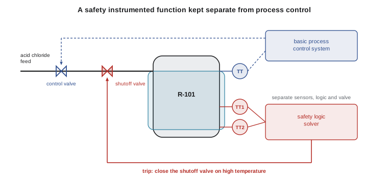
The process industry standard for SIS is IEC 61511, Functional safety: Safety instrumented systems for the process industry sector. It is adopted in the United States as ANSI/ISA-61511 and is widely treated by OSHA and industry as recognized and generally accepted good engineering practice under PSM. It sets out a safety life cycle from hazard and risk assessment, through allocation of safety functions to protection layers, design, installation, validation, operation, maintenance and modification, to decommissioning.
IEC 61511 uses safety integrity levels (SIL) to express how much risk reduction a SIF must provide. For functions that are demanded rarely (low demand mode, less than once a year), each SIL corresponds to a band of average probability of failure on demand.
| SIL | Average PFD (low demand) | Risk reduction factor |
|---|---|---|
| 1 | 0.1 to 0.01 | 10 to 100 |
| 2 | 0.01 to 0.001 | 100 to 1,000 |
| 3 | 0.001 to 0.0001 | 1,000 to 10,000 |
| 4 | 0.0001 to 0.00001 | 10,000 to 100,000 (rare in the process industry) |
The SIL a function needs comes from the risk assessment. In the LOPA example in Lesson 7, if the other layers left a gap of a factor of 50, the trip would need a risk reduction factor of at least 50, which means a SIL 1 design with a PFD of 0.02 or better, or a SIL 2 design for margin.
How SIF reliability is estimated
A SIF fails dangerously when a component fails in a way that stops it acting, such as a valve stuck open, and the failure is not revealed until the next proof test. For a single component in low demand mode, a common simplified estimate is that the average PFD is half the dangerous undetected failure rate multiplied by the proof test interval.
Redundancy lowers the PFD. In a one-out-of-two (1oo2) arrangement, either of two sensors can trip the system, so both must fail. But redundant components often share causes, such as the same calibration error or plugged impulse line, so a common cause factor, beta, is added. The calculation below compares options for the R-101 trip; full verification uses IEC 61511 methods and is covered in more depth in ROB-450.
# Simplified PFDavg for SIF architectures (low demand, illustrative failure rates).
HOURS_PER_YEAR = 8760

def pfd_1oo1(lam_du, ti):
    return lam_du * ti / 2

def pfd_1oo2(lam_du, ti, beta):
    independent = ((1 - beta) * lam_du * ti) ** 2 / 3
    common = beta * lam_du * ti / 2
    return independent + common

sensor = 2e-6 * HOURS_PER_YEAR           # dangerous undetected failures per year (2e-6 per hour)
logic = 1e-7 * HOURS_PER_YEAR
valve = 4e-6 * HOURS_PER_YEAR
ti = 1.0                                  # proof test interval, years

for label_, s_pfd in [("1oo1 sensor", pfd_1oo1(sensor, ti)),
                      ("1oo2 sensors, beta 10%", pfd_1oo2(sensor, ti, 0.10))]:
    total = s_pfd + pfd_1oo1(logic, ti) + pfd_1oo1(valve, ti)
    sil = 1 if total < 0.1 else 0
    sil = 2 if total < 0.01 else sil
    sil = 3 if total < 0.001 else sil
    print(f"{label_:<24} PFDavg {total:.4f}  RRF {1 / total:5.0f}  meets SIL {sil}")

# Effect of stretching the proof test interval to 3 years
total3 = pfd_1oo2(sensor, 3, 0.10) + pfd_1oo1(logic, 3) + pfd_1oo1(valve, 3)
print(f"1oo2 sensors, 3-year test PFDavg {total3:.4f} RRF {1 / total3:5.0f}")1oo1 sensor PFDavg 0.0267 RRF 37 meets SIL 1 1oo2 sensors, beta 10% PFDavg 0.0189 RRF 53 meets SIL 1 1oo2 sensors, 3-year test PFDavg 0.0572 RRF 17
Two lessons follow. The final element, here the valve, often dominates, so adding redundant sensors only helps so much. And proof testing matters: stretching the test interval from one year to three roughly triples the PFD. A SIL rating is not a property of the hardware alone; it depends on testing, maintenance and the way the function is operated.
Bypasses, overrides and impairments
Safeguards are often defeated deliberately. Trips are bypassed during startup when readings are abnormal, during maintenance, or because they trip too often. A bypassed trip provides no protection. Many major accidents involved safeguards that were bypassed, out of service or never tested.
| Control | Purpose |
|---|---|
| Written bypass authorization with a defined approver | Makes bypassing a deliberate, visible decision |
| Risk assessment and compensating measures | Provides alternative protection, such as a dedicated operator watching a local gauge |
| Time limit and automatic expiry | Prevents bypasses becoming permanent |
| Bypass log reviewed at each shift handover | Keeps everyone aware of what is impaired |
| Indication in the control room | Shows bypass status at a glance |
| Tracking repeated or long bypasses as a leading indicator | Reveals spurious trips and design problems |
Worked problem
A spurious trip problem
The R-101 high-temperature trip has tripped the feed six times in three months with no real high temperature. Operators have started bypassing it at the start of each batch. What should the site do?
Show solution
- Treat the bypassing as a sign of a design or maintenance problem, not only an operator discipline issue.
- Investigate the spurious trips: sensor fault, wiring, set point too close to normal operation, or a real but brief temperature spike.
- While the problem is investigated, apply a formal bypass authorization with compensating measures and a time limit, or stop feeding until the trip is reliable.
- Fix the cause, for example replacing a faulty sensor or adding 2oo3 voting to reduce spurious trips while keeping safety integrity.
- Record the issue and track bypass hours and spurious trip rates as leading indicators (Lesson 12).
Answer: Find and fix the cause of the spurious trips while controlling any bypass formally; never let routine informal bypassing continue.
Common mistakes
MistakeSizing the relief device for fire and assuming that covers every case.
InsteadSize for the worst credible case, including runaway and two-phase flow.
MistakeUsing the control system sensor for the safety trip.
InsteadKeep the SIF independent of the basic process control system.
MistakeBuying SIL-rated hardware and calling the function SIL 2.
InsteadAchieve the SIL through the whole life cycle, including proof testing and maintenance.
MistakeAdding redundant sensors without considering common cause.
InsteadInclude common cause failures and look at the final element too.
MistakeAllowing informal bypasses to deal with nuisance trips.
InsteadFix the cause and control any bypass with authorization, time limits and compensating measures.
Summary and key terms
- Safeguards range from inherent and passive, which are most robust, to active and procedural.
- Relief devices must be sized for the worst credible case, including runaway reactions, and discharge to a safe place.
- A safety instrumented function consists of sensors, a logic solver and final elements, and should be independent of process control.
- IEC 61511 sets the safety life cycle for SIS in the process industry; SIL bands express required risk reduction.
- Average PFD depends on failure rates, redundancy, common cause and the proof test interval.
- Bypasses and impairments remove protection and need formal control.
- Passive safeguard
- A safeguard that works without energy or action, such as a dike.
- Relief valve
- A device that opens at a set pressure and recloses when pressure falls.
- Rupture disc
- A non-reclosing device that bursts at a set pressure.
- DIERS
- Design Institute for Emergency Relief Systems, which developed methods for two-phase and reactive relief.
- Safety instrumented system
- Sensors, logic solvers and final elements that take the process to a safe state.
- Safety instrumented function
- One specific protective action carried out by a SIS.
- SIL
- Safety integrity level, a band of required risk reduction.
- Proof test
- A test that reveals dangerous undetected failures in a SIF.
- Common cause failure
- A single cause that defeats redundant components together.
- Bypass
- Deliberately defeating a safeguard, temporarily or otherwise.
Practice problems
Work each problem on paper first, then reveal the answer to check.
Rank inherent, procedural, passive and active safeguards from most to least robust.
Show answer
Inherent, passive, active, procedural.
What is the difference between a relief valve and a rupture disc?
Show answer
A relief valve recloses; a rupture disc bursts and stays open.
Why can a runaway reaction need a larger relief area than the fire case?
Show answer
It may generate heat faster and produce two-phase flow, which needs more area.
Name the three main parts of a SIF.
Show answer
Sensor, logic solver, final element.
What PFD band corresponds to SIL 2 in low demand mode?
Show answer
0.01 to 0.001.
A component has a dangerous undetected failure rate of 0.02 per year and is tested yearly. Estimate its PFDavg.
Show answer
0.02 × 1 / 2 = 0.01.
What happens to PFDavg if the test interval doubles?
Show answer
It roughly doubles.
Why include a beta factor in redundant designs?
Show answer
To account for common cause failures that defeat both channels at once.
Which standard covers SIS in the process industry?
Show answer
IEC 61511.
List three controls for bypasses.
Show answer
Authorization, compensating measures, time limits (also logs, indication and tracking).
Lesson quiz · 5 questions
Score 60% or more to complete this lesson.
Create a free account to save your progress, take quizzes and earn a certificate.