
GEOM-360 · Lesson 7 of 12 · 21 min
Motion sensors
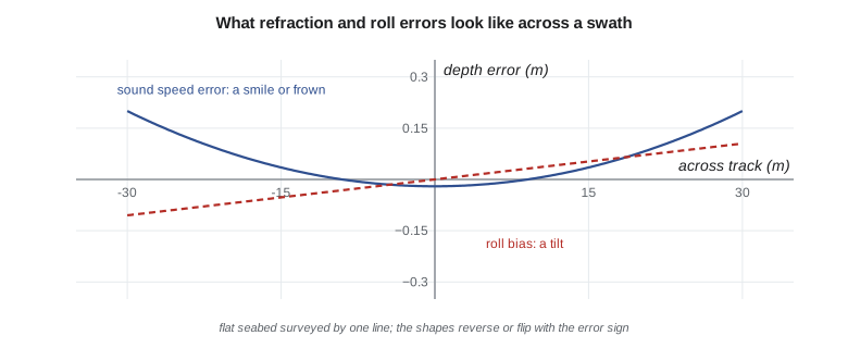
A survey launch is never still. Waves and wakes roll it from side to side, pitch it bow to stern and lift it up and down; the helmsman's corrections and the wind swing its heading. Each of these motions moves the transducer and changes the direction in which each beam points. At the outer edge of a multibeam swath in 17 m of water, a roll error of a tenth of a degree moves the sounding several centimeters vertically, and an unmeasured roll of two degrees would move it more than a meter. Measuring the vessel's motion, and calibrating how the sonar is aligned with the motion sensor, is therefore as important as measuring depth.
The six motions
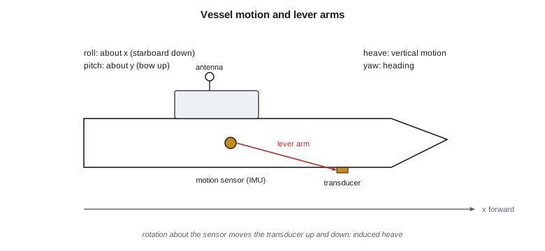
A rigid vessel has six degrees of freedom. Three are rotations: roll about the fore-and-aft axis, pitch about the athwartships axis, and yaw about the vertical axis, which together with the vessel's course gives its heading. Three are translations: surge (forward and back), sway (side to side) and heave (up and down). For hydrography, roll, pitch, heading and heave matter most; surge and sway are absorbed into the GNSS position. Conventions differ between manufacturers, and a sign error in roll or pitch, the most common integration mistake, shows up immediately as a swath that tilts the wrong way when the vessel rolls. The launch's system defines x forward, y to starboard and z down, roll positive with the starboard side down and pitch positive with the bow up.
Inertial motion sensors
A motion sensor, or inertial measurement unit (IMU), contains three accelerometers and three gyroscopes on orthogonal axes. The gyroscopes measure rates of rotation, which are integrated into roll, pitch and heading; the accelerometers measure specific force, from which gravity's direction (and so the long-term reference for roll and pitch) and the vertical acceleration (integrated twice into heave) are derived. Survey-grade units use fiber-optic or ring-laser gyroscopes for the best performance, or high-quality micro-electromechanical sensors in compact units, and achieve roll and pitch accuracies of a few hundredths of a degree. Heading comes from the gyroscopes aided by a dual-antenna GNSS baseline, since magnetic compasses are useless on a steel or aluminum hull full of electronics.
Heave measured from accelerometers alone is a filtered quantity. Double integration of acceleration drifts without limit, so the sensor applies a high-pass filter that keeps the wave-frequency motion and rejects slow changes. That works well in regular waves of short period, but long swells, slow changes in the vessel's trim and turns can leak through or be suppressed. Many systems add delayed heave, computed by filtering forward and backward in time over a few minutes, which is more accurate than real-time heave; and, as Lesson 6 showed, GNSS heights in an ellipsoid-referenced survey replace filtered heave with an absolute measurement of the vessel's vertical position.
Lever arms and induced heave
The motion sensor measures rotation and heave at its own location. The transducer, the GNSS antennas and the reference point of the vessel are elsewhere, and their positions in the vessel frame are the lever arms, measured in the dimensional survey with a total station to a centimeter or better. When the vessel rotates, a transducer offset from the sensor moves up and down: a transducer 4.2 m forward of the sensor drops 0.15 m when the bow pitches down 2°, even if the sensor itself does not move. This induced heave must be computed from the lever arm and the measured angles and applied to each ping. Errors in lever arms produce depth errors that correlate with the vessel's motion and its heading, and they are hard to find later, which is why the dimensional survey is done carefully and documented.
import math
# Motion sensor (IMU) mounted close to the point the vessel rotates about; transducer 4.2 m forward, 1.1 m to starboard
fwd, stbd = 4.2, 1.1
# Induced heave: a lever arm turns rotation into vertical motion at the transducer
for roll, pitch in ((3.0, 0.0), (0.0, 2.0), (3.0, 2.0)):
    r, p = math.radians(roll), math.radians(pitch)
    dz = -fwd * math.sin(p) + stbd * math.sin(r) * math.cos(p)   # positive down (starboard down roll, bow up pitch)
    print(f"roll {roll:+.1f} deg, pitch {pitch:+.1f} deg: induced heave at the transducer {dz:+.3f} m")

# Effect of a roll bias on an outer beam: depth and across-track position
depth, beam = 17.0, 60.0
for bias in (0.05, 0.2):
    a, b = math.radians(beam), math.radians(beam + bias)
    rng = depth / math.cos(a)
    print(f"roll bias {bias:.2f} deg at {beam:.0f} deg: depth error {rng*math.cos(b) - depth:+.3f} m, "
          f"position error {rng*math.sin(b) - rng*math.sin(a):+.3f} m")

# Patch test for roll: two opposite lines over a flat bottom; outer beams disagree by delta_z at offset x
x, dz = 25.0, 0.18      # across-track offset of the comparison, m; difference between the two lines, m
roll_bias = math.degrees(math.atan(dz / (2 * x)))
print(f"roll bias from the patch test: {roll_bias:.3f} deg")
# Latency: a time offset between the motion data and the pings shows up as wobble in fast rolls
rate, lat = 6.0, 0.010    # roll rate deg/s, latency s
err_angle = rate * lat
print(f"a {lat*1000:.0f} ms latency at {rate:.0f} deg/s roll rate gives a {err_angle:.2f} deg roll error, "
      f"{depth * math.tan(math.radians(beam)) * math.radians(err_angle):.3f} m vertical at the outer beam")
# Pitch bias from two lines run in opposite directions over a slope or a target
shift, d2 = 0.12, 17.0     # along-track shift of a target between the two lines, m
print(f"pitch bias from the patch test: {math.degrees(math.atan(shift / (2 * d2))):.2f} deg")
# Yaw bias from a target seen by outer beams on parallel lines in the same direction
dx, off = 0.15, 22.0
print(f"yaw (heading) bias from the patch test: {math.degrees(math.atan(dx / (2 * off))):.2f} deg")roll +3.0 deg, pitch +0.0 deg: induced heave at the transducer +0.058 m roll +0.0 deg, pitch +2.0 deg: induced heave at the transducer -0.147 m roll +3.0 deg, pitch +2.0 deg: induced heave at the transducer -0.089 m roll bias 0.05 deg at 60 deg: depth error -0.026 m, position error +0.015 m roll bias 0.20 deg at 60 deg: depth error -0.103 m, position error +0.059 m roll bias from the patch test: 0.206 deg a 10 ms latency at 6 deg/s roll rate gives a 0.06 deg roll error, 0.031 m vertical at the outer beam pitch bias from the patch test: 0.20 deg yaw (heading) bias from the patch test: 0.20 deg
A 3° roll to starboard lowers the transducer, mounted 1.1 m to starboard of the sensor, by 0.058 m; a 2° bow-up pitch raises it, 4.2 m forward, by 0.147 m. These are not errors if they are computed and applied, but they show why an accurate lever arm matters: an error of 10 cm in the forward offset would leave a 3.5 mm error per degree of pitch. A roll bias of 0.05° moves a 60° sounding at 17 m by 2.6 cm vertically and 1.5 cm across track, within tolerance; a bias of 0.2° moves it by 10 cm, which would show as a tilt between overlapping lines. A 10 ms timing offset at a roll rate of 6° per second produces 0.06° of roll error, 3 cm at the outer beam, varying with every roll.
Alignment and the patch test
The transducer and the motion sensor are bolted to the hull or a pole, and no installation aligns them perfectly. The small angular misalignments between the sonar's axes and the motion sensor's axes, the roll, pitch and yaw biases, must be measured. Along with latency, they are determined by a calibration called the patch test, run at the start of every survey and whenever equipment is moved. It uses pairs of lines chosen so that each bias produces a distinctive, measurable signature, and it is done in a set order, because each bias can mimic another.
Latency is tested first, by running the same line up a slope or over a distinctive object at two very different speeds: a timing error shifts the feature along track by an amount proportional to speed. Pitch bias comes next: the same line is run in opposite directions over a slope or object at the same speed, and a pitch bias displaces the feature along track in opposite senses on the two lines. Roll bias uses a flat seabed: the same line is run in opposite directions, and a roll bias tilts each swath in opposite senses, so that the outer beams disagree by an amount growing with distance from the track. Yaw bias uses an object or slope seen by the outer beams of two parallel lines run in the same direction, offset so that the object lies on opposite sides of the two swaths: a yaw bias rotates each swath and moves the object along track in opposite senses.
For each bias, the angle follows from the geometry. For roll, if the two lines' depths at an across-track offset \(x\) differ by \(\Delta z\), each line is tilted by half the difference, and
Similar half-difference formulas give pitch and yaw from along-track shifts. On the berth, the launch's outer beams 25 m from the track disagree by 0.18 m over a flat area, giving a roll bias of 0.206°; a target's along-track shift of 0.12 m in 17 m of water gives a pitch bias of 0.20°, and an along-track shift of 0.15 m at 22 m across track gives a yaw bias of 0.20°. Leah enters the values into the processing software, reprocesses the patch test lines, and confirms that the biases have disappeared. Modern software also offers automated calibration, which solves for all biases at once by minimizing the differences between overlapping swaths; Leah runs it as a check on her manual values.
Motion artifacts in the data
Errors in motion compensation leave their own signatures. Uncompensated or wrongly signed roll makes the swath rock in time with the vessel's roll, producing a seabed that looks corrugated across track. A roll or heave latency produces a similar wobble but smaller and lagged. Heave errors from long swells or sharp turns raise or lower whole pings, producing ribs along track. Errors in the lever arm produce depth errors that change with the vessel's attitude and look like noise until lines in different directions are compared. Recognizing these patterns lets the processor tell whether to fix a timing setting, a sign, a lever arm or a filter, rather than smoothing the artifacts away.
Practical motion
Good data begin with good boat handling. The helmsman keeps the speed steady, the turns wide and the lines straight, because sharp turns upset heave filters and steep rolls push outer beams beyond their useful angles. Many systems can stabilize the swath against roll by steering the beams electronically, and some against pitch and yaw by steering the transmit pulse, which keeps the soundings evenly spaced on the seabed. Weather limits apply: when the launch rolls more than a few degrees in a short chop, Mira stops the survey, because even perfect motion compensation cannot fix pings whose outer beams are pointing at the sky.
On the reservoir, the project's small boat has no motion sensor, and the single-beam sounder's transducer sits directly below the GNSS antenna on a pole. In the light chop of an autumn morning the boat rolls a few degrees; with an 8° beam on a smooth bottom the effect on depth is small, and the GNSS heights take care of the boat's heave. Grant still logs a simple tilt sensor so that soundings taken while the boat was rolling heavily, in the wake of the project's maintenance boat, can be recognized and rejected.
Worked problem
Roll bias from a patch test
Two lines run in opposite directions over a flat seabed in 20 m of water. At 30 m across track, their depths differ by 0.21 m. Find the roll bias and the vertical error it causes at a beam 60° from nadir.
Show solution
- \[\delta = \arctan\frac{0.21}{2 \times 30} = 0.20^\circ\]
- \[\Delta z \approx d\tan 60^\circ \times \delta_{\text{rad}} = 20 \times 1.732 \times 0.00349 = 0.12\ \text{m}\]
Answer: The roll bias is about 0.20°, which would cause about 0.12 m of vertical error at the 60° beam if left uncorrected.
Common mistakes
MistakeRunning the patch test in a random order.
InsteadDo latency, then pitch, then roll, then yaw; each bias can mimic another.
MistakeCalibrating roll over a sloping or rough seabed.
InsteadUse a flat area so the tilt comes only from the bias.
MistakeMeasuring lever arms with a tape measure along the deck.
InsteadSurvey them in the vessel frame with a total station and document them.
MistakeTrusting real-time heave in long swell.
InsteadUse delayed heave or GNSS heights.
Summary and key terms
- Roll, pitch, heading and heave are measured by an IMU aided by GNSS.
- Accelerometer heave is high-pass filtered; delayed heave and GNSS heights do better.
- Lever arms turn rotation into induced heave at the transducer and must be surveyed carefully.
- The patch test measures latency, pitch, roll and yaw biases with paired lines.
- Roll bias = arctan(Δz / 2x) from opposite lines over a flat seabed.
- Motion errors leave signatures: rocking, wobble, ribs and attitude-dependent noise.
- IMU
- Inertial measurement unit: accelerometers and gyroscopes measuring motion.
- Heave
- Vertical motion of the vessel.
- Induced heave
- Vertical motion at an offset point caused by the vessel's rotation.
- Patch test
- A calibration with paired survey lines to find latency and alignment biases.
- Roll bias
- A fixed angular misalignment between sonar and motion sensor about the fore-and-aft axis.
- Delayed heave
- Heave computed by filtering forward and backward in time.
- Dimensional survey
- Measuring the positions of sensors in the vessel frame.
Practice problems
Work each problem on paper first, then reveal the answer to check.
A transducer is 3.0 m forward of the IMU. How far does it rise for a 1.5° bow-up pitch?
Show answer
About 0.079 m.
Which bias is found by running one line twice in opposite directions over a flat seabed?
Show answer
Roll bias.
Why is latency tested before pitch?
Show answer
A latency error shifts features along track and would be mistaken for pitch bias.
What artifact does a wrong roll sign produce?
Show answer
The swath rocks in time with the vessel's roll.
Why is delayed heave better than real-time heave?
Show answer
It filters with data from both before and after each moment.
Lesson quiz · 5 questions
Score 60% or more to complete this lesson.
Create a free account to save your progress, take quizzes and earn a certificate.