
GEOM-340 · Lesson 11 of 12 · 24 min
Coordinate transformations in software
Very few people compute projections by hand. GIS programs, survey software, CAD packages, GNSS controllers, databases and web services all transform coordinates, mostly through a handful of shared libraries. Theo Martel, who maintains the district's spatial database and scripts, discovered how much depends on the details when two copies of the same turnout layer, reprojected by two different programs, disagreed by 1.4 m. Both programs were 'right': each had chosen a different transformation between the same two datums, and neither had said so. This lesson describes how software represents coordinate reference systems and transformations, how it chooses among them, and how to control and check the result.
The EPSG registry
The EPSG Geodetic Parameter Dataset, begun by the European Petroleum Survey Group and maintained today by the International Association of Oil and Gas Producers (IOGP), is the common dictionary of geodesy in software. It records ellipsoids, datums and frames, coordinate systems and their axes, projections and their parameters, units, conversions and transformations, each with a numeric code, an area of use and, for transformations, an accuracy. Software refers to these objects by code: a layer stored with 'EPSG:6341' is understood everywhere as NAD83(2011) / UTM zone 12N, and a transformation code identifies exactly which method and parameters were used. Codes are permanent; when an entry is found to be wrong, it is deprecated and replaced, not changed.
| EPSG code | Object | Kind |
|---|---|---|
| 6318 | NAD83(2011) | Geographic CRS |
| 6341 | NAD83(2011) / UTM zone 12N | Projected CRS |
| 32100 | NAD83 / Montana | Projected CRS, meters |
| 4326 | WGS 84 | Geographic CRS, latitude first |
| 3857 | WGS 84 / Pseudo-Mercator | Projected CRS for web tiles |
A code is only as good as its use. Some projected systems in common use, such as many low-distortion and county systems, have no EPSG code, and are defined in software by their full parameters; others have several codes for the same projection on different datum realizations, which look alike and give results that differ by centimeters to meters. A code can be found by searching the registry or a mirror of it by name, area or parameters, and the safe habit is to read the full definition rather than trusting the name.
Well-known text and PROJ
A CRS is written out in full as well-known text (WKT), a structured text format standardized by OGC and ISO. The current version, WKT2 (ISO 19162), names every component: the datum and its ellipsoid, the prime meridian, the conversion method and each parameter with its unit, the coordinate system with each axis's name, direction and unit, and optionally the area and scope of use. Older WKT1 strings and the compact parameter strings of the PROJ library ('+proj=tmerc +lon_0=-114 ...') are still met in older files; they lose information, in particular the datum's identity and the axis order, and should be read with care.
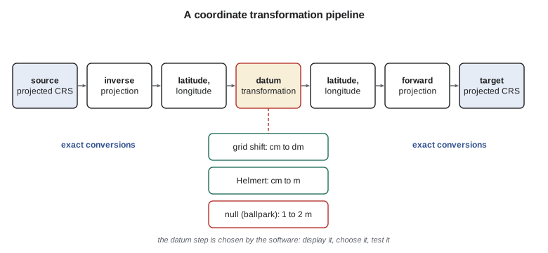
PROJ, an open-source library begun at the US Geological Survey in the 1980s, is used by QGIS, GDAL, PostGIS and many commercial programs to perform the actual computations. Since version 6 (2019), PROJ works from the EPSG database and chooses transformations itself. Between two CRSs it finds every published route, ranks them by accuracy and area of use, and uses the best one whose grids are available. Each route is expressed as a pipeline of steps, for example: inverse UTM projection, conversion to Cartesian coordinates, a Helmert transformation, conversion back to latitude and longitude, forward projection into the target system. The pipeline that was used can be displayed, and it is the most useful single piece of information when two results disagree.
When software chooses for you
The disagreement Theo found had a simple cause. One program had access to the grid-shift file for the datum change and used it; the other did not have the grid installed, fell back on a seven-parameter Helmert with an accuracy of about 1.5 m, and reported no warning. PROJ calls such fallback routes 'ballpark' transformations when they consist only of a change of ellipsoid or a null transformation, and current versions warn when they are used, but many programs hide the warning. Grids are distributed separately from the software, from a content delivery network or as data packages, and an installation may have some and lack others.
Four rules prevent most problems. Make sure the grids needed for the district's transformations are installed on every machine and server. Choose the transformation explicitly, by its EPSG code or a stated pipeline, for any work where centimeters matter. Check every new workflow by transforming a few points whose coordinates are published in both systems, such as control monuments. And record, with every derived data set, the source and target CRSs, the transformation used and the date. GIS programs that reproject layers on the fly for display are convenient, but they make the same choices silently; for analysis and data exchange, layers should be transformed deliberately and stored in the project's CRS.
Axis order
The EPSG registry defines the axis order of each CRS, and for many geographic CRSs, including EPSG:4326, the authoritative order is latitude first, then longitude. Most file formats, GIS programs and web interfaces, however, store longitude first, as \(x\), followed by latitude, as \(y\), because that matches the order of easting and northing. GeoJSON requires longitude first. The result is a classic error: a point at latitude 49.70°, longitude −112.83° read in the wrong order lands in Antarctica or off the map entirely, while a cluster of points near the equator and the prime meridian can be swapped without any visible sign. Software libraries offer an option to force 'traditional GIS order'; programmers must know which order each interface uses. The same issue arises with some projected CRSs whose axes are northing first, which includes several national and polar grids.
import math
a = 6378137.0; f = 1 / 298.257222101; e = math.sqrt(f * (2 - f))   # GRS80

def _m(p): return math.cos(p) / math.sqrt(1 - (e * math.sin(p)) ** 2)
def _t(p): return math.tan(math.pi / 4 - p / 2) / ((1 - e * math.sin(p)) / (1 + e * math.sin(p))) ** (e / 2)

class LCC:
    """Lambert conformal conic with two standard parallels (degrees, m)."""
    def __init__(self, lat1, lat2, lat0, lon0, fe=0.0, fn=0.0):
        p1, p2, p0 = map(math.radians, (lat1, lat2, lat0))
        self.n = (math.log(_m(p1)) - math.log(_m(p2))) / (math.log(_t(p1)) - math.log(_t(p2)))
        self.F = _m(p1) / (self.n * _t(p1) ** self.n)
        self.r0 = a * self.F * _t(p0) ** self.n
        self.lon0, self.fe, self.fn = lon0, fe, fn
    def forward(self, lat, lon):
        p = math.radians(lat); r = a * self.F * _t(p) ** self.n
        th = self.n * math.radians(lon - self.lon0)
        E = self.fe + r * math.sin(th); N = self.fn + self.r0 - r * math.cos(th)
        k = r * self.n / (a * _m(p))                  # point scale factor
        return E, N, k, math.degrees(th)               # th is the grid convergence
    def inverse(self, E, N):
        dx, dy = E - self.fe, self.r0 - (N - self.fn)
        r = math.copysign(math.hypot(dx, dy), self.n); th = math.atan2(dx, dy)
        t = (r / (a * self.F)) ** (1 / self.n); p = math.pi / 2 - 2 * math.atan(t)
        for _ in range(30):
            pn = math.pi / 2 - 2 * math.atan(t * ((1 - e * math.sin(p)) / (1 + e * math.sin(p))) ** (e / 2))
            if abs(pn - p) < 1e-15: break
            p = pn
        return math.degrees(p), self.lon0 + math.degrees(th / self.n)
import re

# 1. Read the parameters from a WKT2 definition (a simplified one, as a GIS would export).
wkt = """PROJCRS["NAD83 / Montana (ft)",
  BASEGEOGCRS["NAD83", DATUM["North American Datum 1983",
    ELLIPSOID["GRS 1980",6378137,298.257222101]]],
  CONVERSION["SPCS83 Montana zone (International feet)", METHOD["Lambert Conic Conformal (2SP)"],
    PARAMETER["Latitude of false origin",44.25], PARAMETER["Longitude of false origin",-109.5],
    PARAMETER["Latitude of 1st standard parallel",49], PARAMETER["Latitude of 2nd standard parallel",45],
    PARAMETER["Easting at false origin",1968503.937], PARAMETER["Northing at false origin",0]],
  CS[Cartesian,2], AXIS["easting (X)",east], AXIS["northing (Y)",north], LENGTHUNIT["foot",0.3048]]"""
params = {k: float(v) for k, v in re.findall(r'PARAMETER\["([^"]+)",([-0-9.]+)\]', wkt)}
name = re.search(r'PROJCRS\["([^"]+)"', wkt).group(1)
unit = re.search(r'LENGTHUNIT\["([^"]+)",([0-9.]+)\]', wkt); ft = float(unit.group(2))
print("CRS:", name)
for k, v in params.items(): print(f"  {k:36s} {v:.10g}")
print(f"  length unit: {unit.group(1)} ({ft} m)")

# 2. Use the parsed parameters in a pipeline: degrees -> m -> feet, and back.
proj = LCC(params["Latitude of 1st standard parallel"], params["Latitude of 2nd standard parallel"],
           params["Latitude of false origin"], params["Longitude of false origin"],
           params["Easting at false origin"] * ft, params["Northing at false origin"] * ft)
E, N, k, g = proj.forward(47.50600422, -111.29779092)
la, lo = proj.inverse(E, N)
print(f"\nCR1 -> E {E/ft:.3f} ft  N {N/ft:.3f} ft -> back to {la:.9f}, {lo:.9f}")

# 3. Catch swapped axes: EPSG:4326 and many geographic CRSs list latitude first,
#    but most files and web APIs store longitude first.
district_box = (47.2, 47.8, -111.8, -110.8)          # lat min, lat max, lon min, lon max
def check(points):
    for p in points:
        a1, a2 = p
        if district_box[0] <= a1 <= district_box[1] and district_box[2] <= a2 <= district_box[3]:
            yield p, "lat, lon order: inside the district"
        elif district_box[0] <= a2 <= district_box[1] and district_box[2] <= a1 <= district_box[3]:
            yield p, "lon, lat order: swap before use"
        else:
            yield p, "outside the district: check the CRS"
for p, msg in check([(47.5060, -111.2978), (-111.2912, 47.5104), (1524450.8, 1192102.0)]):
print(f" {str(p):24s} {msg}")CRS: NAD83 / Montana (ft) Latitude of false origin 44.25 Longitude of false origin -109.5 Latitude of 1st standard parallel 49 Latitude of 2nd standard parallel 45 Easting at false origin 1968503.937 Northing at false origin 0 length unit: foot (0.3048 m) CR1 -> E 1524450.750 ft N 1192102.008 ft -> back to 47.506004220, -111.297790920 (47.506, -111.2978) lat, lon order: inside the district (-111.2912, 47.5104) lon, lat order: swap before use (1524450.8, 1192102.0) outside the district: check the CRS
The parser reads the method parameters from the WKT, together with the unit, and the pipeline built from them reproduces CR1's state plane coordinates, E 1,524,450.750 ft and N 1,192,102.008 ft, and returns the original latitude and longitude. The false easting in the definition is given in feet, 1,968,503.937 ft, which is exactly 600,000 m; using the meter value with a foot unit, or the reverse, is a common mistake when definitions are typed by hand. The axis check compares each pair with the district's bounding box in both orders: the first pair is in latitude, longitude order and inside the district, the second is in longitude, latitude order and must be swapped, and the third is not geographic at all; it is a pair of state plane coordinates in feet, which should send the user back to the file's metadata.
Dynamic frames and coordinate epochs in software
Lesson 10 showed that coordinates in ITRF and, at a smaller level, in plate-fixed frames change with time. Software has begun to handle this: the EPSG registry marks frames such as ITRF2020 as dynamic, PROJ can apply time-dependent transformations and velocity grids when it is given a coordinate epoch, and newer formats can store a data set's coordinate epoch with its CRS. Many programs still ignore epochs, which is harmless for GIS at the meter level and harmful for precise work. For GNSS data, the safe practice is to transform to the project's plate-fixed frame and reference epoch at processing time, using the national tools, and to store the result with its epoch written in the metadata.
CAD, GNSS controllers and site calibrations
CAD drawings are a common weak point. Many CAD files carry no CRS at all; their coordinates may be a projected system, a scaled 'ground' system, an arbitrary site grid or a mixture, and only the drawing notes, if any, say which. Before a CAD file is brought into the GIS, its system should be established and tested against features of known position. GNSS controllers used for construction often apply a 'site calibration' or 'localization', a best-fit transformation from GNSS coordinates to the coordinates of a few site control points. A calibration is a legitimate way of fitting a site grid, but it is a transformation fitted to a handful of points, with no formal definition outside the controller, and it should be documented and reused rather than recomputed on every visit. A low-distortion projection, defined once and loaded in every device, avoids most of these issues.
Worked problem
Diagnosing a 1.4 m disagreement
The turnout layer transformed from NAD83(1986) on SPCS 83 to NAD83(2011) in UTM zone 12 differs between two programs by 1.4 m, almost all in one direction. What is the likely cause, and how should it be confirmed?
Show solution
- Projection steps are exact, so a systematic meter-level difference points to the datum step.
- Display the pipeline used by each program; one is likely to use a grid and the other a Helmert or ballpark route.
- Transform two published control points in each program and compare with their published coordinates in the target system.
Answer: The program that reproduces the control within centimeters is using the right route. Install the missing grid on the other machine, rerun, and record the transformation code in the data standard.
Worked problem
Checking a hand-entered definition
A contractor sends a CRS definition for a project TM typed by hand. How can it be checked before use?
Show solution
- Compare every parameter with the published definition: method, central meridian, scale factor, false origin, unit and datum.
- Project a published control point with the definition and compare with its published projected coordinates.
- Inverse-project the result and confirm the original latitude and longitude are returned.
Answer: A definition that passes all three checks can be used. A difference of exactly 500,000 or 1,000,000 units suggests a false easting problem; a difference proportional to the coordinates suggests a scale factor or unit problem.
Common mistakes
MistakeRelying on on-the-fly reprojection for analysis.
InsteadTransform layers deliberately into the project CRS and store them.
MistakeLetting software choose a datum transformation without checking.
InsteadDisplay the pipeline, choose by EPSG code, and test known points.
MistakeAssuming every machine has the same transformation grids installed.
InsteadInstall the grids the project needs everywhere it is processed.
MistakeConfusing latitude-first and longitude-first axis order.
InsteadKnow each interface's order, and check points against the area's bounding box.
MistakeImporting CAD files with no stated coordinate system.
InsteadEstablish and test the system against features of known position first.
Summary and key terms
- The EPSG registry (IOGP) defines CRSs and transformations by permanent codes, with areas of use and accuracies.
- WKT2 (ISO 19162) describes a CRS completely; older strings may lose the datum and axis order.
- PROJ builds transformation pipelines and ranks routes by accuracy; missing grids lead to silent fallbacks.
- Choose and record transformations explicitly and test them with published control.
- Axis order differs between the registry and most software; GeoJSON is longitude first.
- Dynamic frames need coordinate epochs; CAD files and site calibrations need documented systems.
- EPSG registry
- The IOGP database of geodetic parameters, CRSs and transformations.
- WKT2
- Well-known text for CRSs, ISO 19162.
- PROJ
- The open-source library that performs most coordinate operations in GIS software.
- Pipeline
- The ordered sequence of conversions and transformations between two CRSs.
- Ballpark transformation
- A crude fallback, such as a null transformation, used when no better route is available.
- Axis order
- The order of coordinates in a CRS, for example latitude then longitude.
- Site calibration
- A best-fit transformation from GNSS coordinates to local site control.
Practice problems
Work each problem on paper first, then reveal the answer to check.
What does an EPSG transformation record that a conversion does not?
Show answer
An accuracy, because transformations are empirical.
Two programs agree on a reprojection to the millimeter except in one area. What might explain it?
Show answer
A grid that covers only part of the data, or a route chosen by area of use.
Why should hand-typed PROJ strings be avoided for exchange?
Show answer
They can lose the datum identity and axis order; WKT2 is complete.
A web API returns [49.70, −112.83] for a point. Which order is it?
Show answer
Latitude, longitude; check whether your software expects longitude first.
Why is a defined LDP preferable to repeated site calibrations?
Show answer
It has one formal definition used by every device and program.
Lesson quiz · 5 questions
Score 60% or more to complete this lesson.
Create a free account to save your progress, take quizzes and earn a certificate.