
GAS-340 · Lesson 6 of 12 · 22 min
Electrical and control problems
▶ Video coming soon A video version of this lesson is on the way.
One of the commercial work orders in the pile was Maureen Fitch's, from February 2026: a Columbus medical office whose two rooftop units had stopped heating on the same morning. Both units' boards were dark. The building manager had already called the electrician, who found the breakers on and line voltage at both units' disconnects, and left. Maureen found the cause in ten minutes with her meter, because she did not stop at the disconnect. Both units shared a 24-volt control circuit with the building's new energy management system, and the installer of that system had wired a common transformer to both units in a way that put two transformers' secondaries in parallel out of phase. Something had to give, and the fuse on one board had blown, taking the other board's power with it.
Electrical and control faults are where gas technicians most often get lost, because the faults are invisible and the circuits can look complicated. GAS-130 taught the electrical basics and GAS-220 the controls; this lesson puts them to work on service calls. It covers the order in which to check a control circuit, how to read a ladder diagram to find a fault, how to use the board's fault codes and their limits, and the common electrical causes of no-heat calls on furnaces, boilers and rooftop units.
Power first, then the control circuit
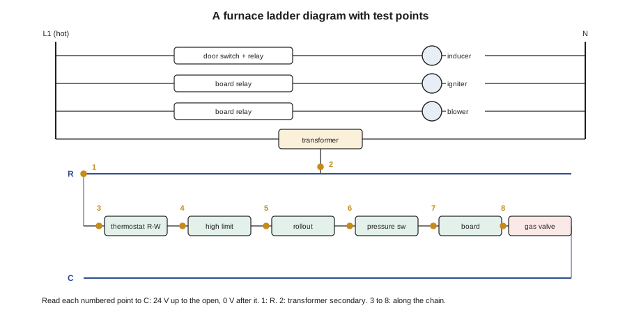
Every electrical diagnosis starts at the supply and works inward. The basics from lesson 2 come first: is there line voltage at the appliance, with the service switch on, the breaker on and the door switch closed? Is there 24 V at the transformer's secondary? Is the thermostat calling? Only then does the technician follow the circuit through the safety chain to the gas valve, using the method from GAS-130: read from a common reference to each point along the circuit, and the open lies between the last point with voltage and the first point without.
- Line voltage: about 120 V from hot to neutral at the appliance, near zero from neutral to ground, and correct polarity.
- Transformer: line voltage on the primary, about 24 to 28 V on the secondary with a light load; a dead secondary with a good primary means a failed transformer or a blown fuse on the secondary side.
- Fuse: most boards have a 3 or 5 ampere automotive-style fuse on the 24 V side. A blown fuse is a symptom; something drew too much current. The cause is found before the fuse is replaced, or the new one blows too.
- Thermostat call: 24 V between W and C at the board with the thermostat calling for heat; a missing call with 24 V at R points to the thermostat or its cable.
- Safety chain and valve: voltage to common at each switch in turn, then at the gas valve terminals during the trial.
Reading the circuit, not the code
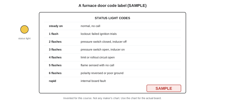
Modern control boards help by flashing a code or showing a message for the fault they detect, and the code chart, usually printed on the furnace door or in the manual, says what the code means. Codes are a start, not an answer. A code tells the technician which input the board saw misbehave: the pressure switch, the limit circuit, the flame signal. It does not say why. A "limit open" code can mean a failed limit, a dirty filter, a blower running slowly, closed registers, a weak blower capacitor or an overfired burner. A "pressure switch open" code can mean any of the causes in lesson 5.
Code charts also differ between makers and even between models from the same maker, so the chart for the actual board is always used. The sample chart below is invented for this course to show how charts are laid out; it is not any maker's chart.
| Flashes | Board reports (SAMPLE chart) | What it really means to check |
|---|---|---|
| Steady on | Normal, no call | — |
| 1 | Lockout after failed ignition trials | Ignition and flame proving (lesson 4) |
| 2 | Pressure switch closed with inducer off | Stuck switch, wrong wiring, wind |
| 3 | Pressure switch open with inducer on | Suction at switch and tap (lesson 5) |
| 4 | Limit or rollout circuit open | Airflow, filter, blower, overfiring, rollout cause |
| 5 | Flame sensed with no call | Gas valve leaking through: urgent |
| 6 | Polarity reversed or poor ground | Supply wiring, neutral, ground |
| Rapid | Internal board fault | Confirm inputs and supply before replacing the board |
Common electrical causes of no heat
A few electrical faults account for most of the electrical no-heat calls, and they are worth checking early:
- A door switch that is not being pushed closed because the blower door is not seated properly, or that has failed open.
- Loose, burnt or corroded connections, especially at line voltage terminals, the transformer and the gas valve. A connection can read correct voltage with no load and drop out under load, so readings are taken with the appliance running or calling.
- A blown board fuse, caused by a chafed thermostat cable shorting to the cabinet, a shorted gas valve coil, a shorted zone valve, or a new accessory such as a humidifier wired to the 24 V circuit without considering the transformer's capacity.
- Overloaded transformers, the GAS-130 Aberdeen case: too many zone valves or accessories on a transformer too small for them, so that the voltage sags under load.
- Reversed polarity or a floating neutral, which upsets flame rectification and makes boards lock out on flame failure.
- Failed capacitors on blower and inducer motors, which make motors hum, start slowly or run hot and trip their internal overloads.
- Damaged thermostat cable, from rodents, a drywall screw, as in the GAS-130 case study, or a crushed run.
Worked problem
Is the transformer big enough?
A furnace's transformer is rated 40 VA. On a call, the technician measures, with the system calling for heat and cooling at once as the thermostat allows, these currents on the 24 V side: gas valve 0.5 A, board 0.3 A, humidifier solenoid 0.4 A, condensing unit contactor 0.35 A, and a new zone damper motor the homeowner added, 0.4 A. The secondary voltage under that load is 23.5 V. Is the transformer overloaded?
Show solution
- Total current on the secondary:
- \[0.5 + 0.3 + 0.4 + 0.35 + 0.4 = 1.95 \text{ A}\]
- Load in volt-amperes:
- \[1.95 \times 23.5 \approx 45.8 \text{ VA}\]
- Compare with the rating:
- \[45.8 \text{ VA} > 40 \text{ VA}\]
Answer: The transformer is about 15 in 100 overloaded. It will run hot, its voltage will sag and it may fail, or blow the board fuse. Either the damper motor gets its own transformer, or a larger transformer approved for the furnace is fitted.
Maureen's rooftop units
At the medical office, Maureen started where the electrician had stopped. Line voltage at each unit's disconnect was correct, but at each unit's board she found no 24 V on the secondary. Unit 1's transformer primary had line voltage and its secondary was dead; its board fuse was blown. Unit 2's transformer was good, but its board was also dark. Following the wiring, she found that the energy management installer had connected each unit's R and C terminals to a shared relay panel, tying the two units' 24 V circuits together. The two transformers' secondaries were now connected in parallel, and with their primaries on different phases of the building's supply, they fought each other. GAS-130 taught the rule this broke: never tie two transformers' secondaries together unless the maker allows it and they are phased correctly.
Maureen isolated each unit's control circuit from the shared panel, replaced unit 1's fuse and transformer, and restored heat. She then wrote to the building manager and the energy management installer, with a sketch, explaining that each unit's controls had to be wired through isolated contacts, relays with separate coils and contacts, so that the two 24 V circuits never connected. The installer rewired the panel that week, and Maureen came back to check both units through full heating cycles before signing off.
When to replace a board
Control boards do fail, but they are replaced far more often than they fail. A board is condemned only after the technician has proved that it has the right inputs and is not giving the right outputs. If the board has 24 V and a call at W, sees the pressure switch closed, and still does not energize the igniter after its pre-purge, and the wiring to the igniter is good, the board is at fault. If an input is missing, the board is doing its job. Burnt traces, a swollen relay or a smell of burning on the board itself are clear signs of failure, and the cause, often a shorted motor or valve, must be found before the new board is fitted, as the GAS-220 Waterdown case showed with a seizing inducer that had welded the board's relay.
A replacement board is set up before it goes into service: the dip switches or menu settings for blower delays, staging and accessories set to match the old board or the maker's instructions for that furnace model, and the wiring transferred one wire at a time with labels. After replacement, the furnace is run through its full sequence and every safety control is tested.
Motors and capacitors
Blower and inducer motors cause a large share of electrical service calls, and their faults are easy to misread. A motor that hums but does not start, starts slowly, runs hot and trips its internal overload, or runs at the wrong speed may have a failed bearing, a failed winding, a failing run capacitor or the wrong speed tap selected. Each is checked with a meter rather than guessed. The run capacitor, on permanent split capacitor motors, is discharged safely with a resistor and measured with the meter's capacitance range; GAS-130's Garfield case found one at 4.1 of its rated 7.5 microfarads. The motor's running current is compared with its nameplate. And the motor is turned by hand with the power off to feel for tight or rough bearings.
Electronically commutated motors, ECMs, are now common in furnaces and air handlers. They have their own control modules, and they are diagnosed by the maker's procedure: checking the line voltage at the motor, the control signals from the furnace board, and sometimes the module with the maker's test tool. An ECM that will not run with correct power and signals has failed; its module can sometimes be replaced on its own. An ECM is never tested by applying line voltage to its control terminals, which can destroy it.
| Motor symptom | First checks |
|---|---|
| Hums, will not start | Run capacitor, seized bearing, power at the motor |
| Starts, trips on overload after a while | Capacitor, bearings, current against nameplate, airflow |
| Runs at the wrong speed | Speed tap selection, board settings, ECM programming |
| ECM will not run | Line voltage at the motor, control signals, maker's test procedure |
| Runs but airflow is low | Filter, blower wheel dirt, duct restrictions, speed setting |
Motor faults often show up first as other faults. A weak blower makes the heat exchanger overheat and the limit trip; a weak inducer makes the pressure switch open. That is why lesson 2's step 7, find the cause, matters: the limit that trips is the messenger, the motor is the cause, and the filter or the dirty blower wheel may be the cause of the motor's failure.
Thermostats and communicating controls
Thermostats cause more no-heat calls than they should. A thermostat set to cool, set to a schedule the owner forgot, or with dead batteries is a basic check from lesson 2. Wi-Fi thermostats that steal power through the heating circuit when there is no common wire can make some furnaces cycle oddly or fail to start; the cure is a common wire, as GAS-130 described. A thermostat can be ruled in or out in seconds by jumpering R to W at the furnace board with the thermostat disconnected: if the furnace starts its sequence, the fault is in the thermostat or its cable, not the furnace.
Communicating systems, in which the thermostat, furnace and outdoor unit exchange data over two or four wires rather than switching 24 V on separate terminals, need the maker's diagnostic procedure. Their faults show as communication errors, and the usual causes are wiring polarity, a loose terminal or a component that has lost its configuration. A communicating thermostat cannot be tested by jumpering R to W in the usual way, and the maker's instructions say how to test it.
Common mistakes
MistakeStopping the diagnosis at the disconnect because line voltage is there.
InsteadFollow the circuit to the transformer, board, call and safety chain.
MistakeReplacing a blown board fuse without finding the short.
InsteadFind what drew too much current first.
MistakeTaking a fault code as the answer.
InsteadA code names the input that failed; test to find why.
MistakeUsing another maker's code chart.
InsteadUse the chart for the actual board.
MistakeAdding accessories to a 24 V circuit without checking the transformer's VA.
InsteadAdd up the load and keep it within the rating.
MistakeReplacing a board that is missing one of its inputs.
InsteadProve the inputs are right and the outputs wrong before condemning it.
Summary and key terms
- Electrical diagnosis works from the supply inward: line voltage and polarity, transformer primary and secondary, the board fuse, the thermostat call, then each point of the safety chain and the gas valve, reading to a common reference so that the open lies between the last point with voltage and the first without.
- Fault codes name the input the board saw fail, not the cause, and only the actual board's chart applies.
- Common causes of no heat are door switches, loose or corroded connections, blown fuses from shorts, overloaded transformers, polarity and neutral faults, failed capacitors and damaged thermostat cable.
- Transformer secondaries are never tied together unless the maker allows it.
- Boards are replaced only when their inputs are proven right and their outputs wrong, after finding what damaged them, and are set up and tested before going into service.
- Ladder diagram
- A wiring diagram drawn as rails and rungs that shows how each load is controlled.
- Common reference
- A point, usually C on the 24 V side, against which voltages along a circuit are read.
- Fault code
- A flashing light or message by which a control board reports the input it saw fail.
- Volt-ampere (VA)
- The rating of a transformer: secondary voltage times the current it can supply.
- Isolation relay
- A relay whose coil and contacts are separate, used to connect controls without joining their circuits.
- Door switch
- A safety switch that cuts power when an appliance's blower door is removed.
Practice problems
Work each problem on paper first, then reveal the answer to check.
Where does an electrical diagnosis start?
Show answer
At the supply: line voltage and polarity at the appliance, then the transformer.
What does a fault code tell you, and what does it not tell you?
Show answer
Which input the board saw fail, not why it failed.
A 40 VA transformer supplies 1.95 A at 23.5 V. Is it overloaded?
Show answer
Yes: 1.95 × 23.5 is about 45.8 VA, more than 40 VA.
What went wrong with Maureen's two rooftop units?
Show answer
Their 24 V circuits were tied together through a shared panel, putting two transformers' secondaries in parallel out of phase.
When is a control board condemned?
Show answer
When its inputs are proven correct and its outputs are wrong, and the cause of any damage has been found.
Lesson quiz · 5 questions
Score 60% or more to complete this lesson.
Create a free account to save your progress, take quizzes and earn a certificate.