
ELEC-320 · Lesson 8 of 12 · 25 min
Grounding and bonding for large services
Grounding and bonding are among the most misunderstood topics in electrical work, partly because the two words describe different jobs that share the same green and bare copper conductors. Grounding connects the electrical system to the earth, which limits voltage from lightning, line surges and contact with higher-voltage lines, and stabilizes the voltage to ground during normal operation. Bonding connects all the non-current-carrying metal parts of the installation together and back to the source, so that a ground fault produces enough current to open the overcurrent device quickly and so that no dangerous voltage exists between metal parts a person could touch at the same time. In a large service, the grounding and bonding system also affects ground-fault protection, power quality, communications and lightning performance. This lesson covers the purposes of grounding and bonding, grounding electrodes and the grounding electrode system, sizing grounding electrode conductors and bonding conductors, main and system bonding jumpers, bonding of metal piping and structural steel, equipment bonding conductors in feeders, and testing electrode resistance.
Why the earth is not the fault path
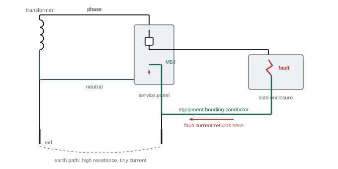
A common misconception is that fault current returns through the earth. Consider a 347/600 V or 277/480 V system with a single ground rod of 25 Ω at the service: a phase-to-enclosure fault returning only through the earth would see the rod resistance plus the utility's grounding resistance, perhaps 30 Ω in total, giving a fault current of about 347 ÷ 30 ≈ 12 A or 277 ÷ 30 ≈ 9 A, far too little to trip a 200 A breaker. The enclosure would sit at a dangerous voltage indefinitely. The fault current must instead return on a low-impedance metallic path: the equipment bonding conductor, conduit or cable armor (where permitted), back to the service, through the main bonding jumper to the neutral, and back to the transformer. The earth connection limits overvoltages; the bonding path clears faults.
Grounding electrodes
A grounding electrode is a conductive object in direct contact with the earth. Codes recognize several types, and generally require that all those present at a building be bonded together to form a single grounding electrode system:
- Metal underground water piping in direct contact with the earth for at least 3 m (10 ft); because plastic pipe may replace it in future, it must be supplemented by another electrode.
- The metal frame of the building where it is effectively grounded through its footings.
- Concrete-encased electrodes (sometimes called Ufer grounds): reinforcing steel or bare copper conductor at least 6 m (20 ft) long, encased in concrete footings in contact with the earth. These are often the best electrodes available and must be planned before the concrete is poured.
- Ground rings: a bare copper conductor buried around the building perimeter.
- Rod and pipe electrodes: copper-clad or galvanized steel rods, typically 3 m (10 ft) long, driven into the earth.
- Plate electrodes: metal plates buried in the earth.
In the United States, NEC 250.50 requires all grounding electrodes present at each building to be bonded together, and 250.52 lists them. A single rod, pipe or plate electrode must be supplemented by a second electrode unless its resistance to earth is 25 Ω or less (250.53(A)(2)), and rods must be at least 6 ft apart. A metal underground water pipe must be supplemented by an additional electrode (250.53(D)).
Grounding electrode conductors
The grounding electrode conductor (GEC) connects the system neutral (and the equipment bonding system) at the service to the grounding electrode system. It is sized from the size of the largest service conductors, not from the overcurrent device rating, because it must withstand the current from a fault to the utility's system, lightning and surges, but it does not carry normal fault-clearing current. GECs are run in one continuous length or spliced only by irreversible compression connectors or exothermic welding, protected from physical damage, and connected to electrodes with listed clamps or exothermic welds that remain accessible where required.
In the United States, NEC Table 250.66 sizes the GEC by the largest ungrounded service conductor: for example, service conductors of 3/0 AWG copper require a 4 AWG copper GEC, and services larger than 1100 kcmil copper require 3/0 AWG copper. The portion of the GEC that connects only to rods, pipes or plates need not be larger than 6 AWG copper, and the portion to a concrete-encased electrode need not be larger than 4 AWG copper (250.66(A) and (B)).
| Conductor | Connects | Carries | Sized from |
|---|---|---|---|
| Grounding electrode conductor | Neutral and bonding system to electrodes | Surge, lightning and utility-side fault current | NEC Table 250.66 |
| Main bonding jumper | Neutral to service enclosure and bonding system | Full ground-fault current | NEC 250.102(C), Table 250.102(C)(1) |
| Supply-side bonding jumper | Service enclosures and raceways ahead of the main | Full ground-fault current | NEC Table 250.102(C)(1) |
| Equipment bonding conductor | Load equipment back to the source | Fault-clearing current | NEC Table 250.122, by overcurrent rating |
The main bonding jumper
At the service, the neutral is connected to the service equipment enclosure and the equipment bonding system by the main bonding jumper, which may be a screw, strap or wire. This is the single point where the neutral and bonding systems join for the service (separately derived systems have their own single point, as in Lesson 7). The main bonding jumper carries the full ground-fault current for any fault on the premises, so it is sized like a supply-side bonding conductor, based on the size of the service conductors, and for very large services it may be a substantial copper bar. Downstream of the service, the neutral must be isolated from enclosures in every panelboard and piece of equipment: neutral bars in subpanels are insulated from the enclosure, and bonding screws supplied with panelboards are removed.
Downstream neutral-to-ground connections are among the most common faults found in commissioning. They divide normal neutral current between the neutral and the bonding path, putting current on conduits, cable trays and building steel; they produce magnetic fields that interfere with sensitive equipment; and they cause ground-fault protection on the main to trip or to fail to see faults. A clamp-on meter around the bonding conductor of a feeder normally reads near zero; a significant current suggests a neutral-to-ground connection or a ground fault downstream.
Equipment bonding conductors
Each feeder and branch circuit needs an equipment bonding conductor (CEC) or equipment grounding conductor (NEC) that returns fault current from the load to the source. It may be a separate copper or aluminum conductor, the metal conduit or EMT itself where permitted, or the armor of a cable listed for the purpose. It is sized from the rating of the overcurrent device protecting the circuit, because it must carry enough current long enough for that device to clear a fault. When phase conductors are increased in size to limit voltage drop, the bonding conductor must generally be increased proportionally, so that the fault-loop impedance remains low enough to trip the breaker.
In the United States, NEC Table 250.122 sizes the equipment grounding conductor from the overcurrent device rating; for example, a 400 A circuit requires 3 AWG copper and an 800 A circuit requires 1/0 AWG copper. Where ungrounded conductors are increased in size for voltage drop, the EGC must be increased proportionally by circular mil area (250.122(B)), and for parallel runs in separate raceways each EGC is sized for the full overcurrent device rating (250.122(F)).
Worked problem
Upsizing a bonding conductor for voltage drop
A 100 A feeder would normally use 3 AWG copper conductors (52,620 cmil) and an 8 AWG copper bonding conductor (16,510 cmil). Because of a long run, the phase conductors are increased to 1/0 AWG (105,600 cmil). What size bonding conductor is required?
Show solution
- Ratio of increase: 105,600 ÷ 52,620 = 2.01.
- Required bonding conductor area: 16,510 × 2.01 = 33,180 cmil.
- 4 AWG copper is 41,740 cmil; 6 AWG is 26,240 cmil (too small).
- Select 4 AWG copper, the next size with at least 33,180 cmil.
Answer: A 4 AWG copper bonding conductor is required, keeping the fault loop impedance low enough over the longer run.
Bonding piping, steel and other systems
Metal piping systems that could become energized must be bonded to the electrical bonding system: interior metal water piping, gas piping (by the circuit bonding conductor of the equipment it serves or by a separate bond, depending on local rules), and other metal piping. Exposed structural steel that is interconnected and could become energized must also be bonded. Communications, cable TV and other low-voltage systems entering the building must be bonded to the same grounding electrode system through an intersystem bonding termination, so that during a lightning strike or utility fault all systems rise in voltage together rather than creating a voltage difference between, for example, a telephone and a grounded appliance. Separate, isolated ground rods for computers or equipment, not bonded to the building system, are dangerous and prohibited: in a lightning strike or fault they create large voltage differences between equipment connected to different systems.
Isolated ground receptacles and circuits are permitted, but the isolated ground conductor runs back to the service or separately derived system bonding point, insulated from the raceway along the way; it is a quieter path to the same single point, not a separate earth.
Testing grounding electrodes
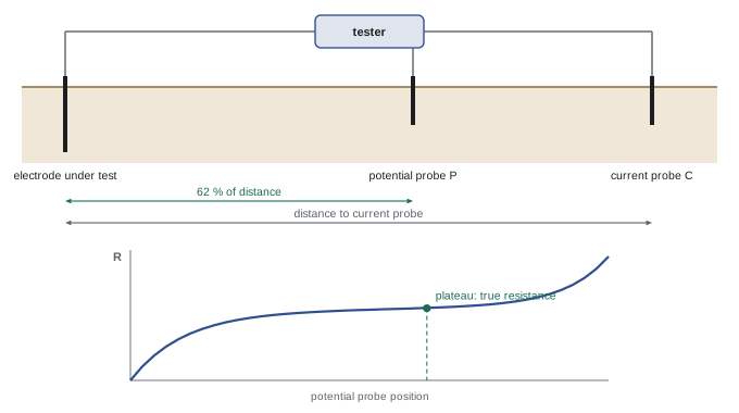
The resistance of a grounding electrode to earth depends on soil resistivity, moisture, temperature and electrode geometry; a single rod in average soil may be 25 to 100 Ω, while a building with a concrete-encased electrode or ground ring may be under 5 Ω. Where specifications or codes call for a maximum resistance, it is measured by the fall-of-potential method: the electrode under test is disconnected from the system (or a clamp-on method is used where disconnection is unsafe), a current probe is driven in the earth some distance away (typically at least five to ten times the electrode depth or diagonal of a grid), and a potential probe is placed at intervals between them. The tester injects current and measures voltage; the resistance plotted against probe distance flattens into a plateau, and the value at about 62 % of the distance to the current probe gives the electrode resistance. Clamp-on testers measure the loop resistance of an electrode in a multi-grounded system without disconnecting it, but they require a parallel return path and cannot test a single isolated electrode. Soil resistivity can be measured with the four-pin Wenner method before design.
Never disconnect a grounding electrode conductor from an energized service: if a fault or utility neutral problem occurs, a dangerous voltage can appear across the opening. Use a clamp-on tester, or test before the service is energized or during a planned outage.
Grounding and bonding inspections
Inspectors and commissioning agents pay close attention to grounding and bonding because errors are common and often invisible once covers are closed. Typical inspection points include the size and routing of the grounding electrode conductor, the type and accessibility of electrode connections, the presence and size of the main bonding jumper, the removal of bonding screws in downstream panels, the bonding of metal piping and structural steel, and the intersystem bonding termination for communications systems. Taking photographs of grounding connections before concrete is poured or walls are closed provides a valuable record.
Common mistakes
MistakeAssuming a ground rod will trip a breaker on a fault.
InsteadFault current must return on bonding conductors to the source.
MistakeBonding neutral to enclosure in subpanels.
InsteadBond only at the service and at each separately derived system.
MistakeLeaving bonding conductors the original size after upsizing phase conductors.
InsteadIncrease the bonding conductor proportionally.
MistakeInstalling isolated ground rods for sensitive equipment.
InsteadBond all electrodes and systems into one grounding electrode system.
MistakeDisconnecting a GEC from an energized service to test it.
InsteadUse a clamp-on tester or test during an outage.
Summary and key terms
- Grounding limits overvoltages; bonding provides the low-impedance path that clears faults and equalizes voltages.
- Fault current returns on metal bonding paths, not through the earth.
- All electrodes present are bonded together into one grounding electrode system; concrete-encased electrodes are excellent.
- GECs are sized from NEC Table 250.66 by service conductor size; EGCs from Table 250.122.
- The neutral is bonded to the bonding system at the service and at each separately derived system only.
- Bonding conductors are increased in proportion when phase conductors are upsized.
- Fall-of-potential testing at 62 % distance measures electrode resistance; clamp-on testers suit multi-grounded systems.
- Grounding
- Connecting the electrical system to the earth.
- Bonding
- Connecting metal parts together to form a continuous low-impedance path.
- Grounding electrode
- A conductive object in contact with the earth.
- Concrete-encased electrode
- Reinforcing steel or copper encased in concrete footings.
- Grounding electrode conductor
- The conductor from the service to the grounding electrode system.
- Main bonding jumper
- The connection between neutral and bonding at the service.
- Equipment bonding (grounding) conductor
- The conductor returning fault current from equipment to the source.
- Intersystem bonding termination
- A point for bonding communications systems to the grounding system.
- Fall-of-potential test
- A three-point method of measuring electrode resistance.
- Soil resistivity
- The resistance of a unit volume of soil, measured by the Wenner method.
Practice problems
Work each problem on paper first, then reveal the answer to check.
What are the purposes of grounding and of bonding?
Show answer
Grounding limits overvoltage and stabilizes voltage to ground; bonding clears faults and prevents touch voltages.
A 277 V fault returns through 30 Ω of earth. What current flows?
Show answer
About 9 A, not enough to trip a large breaker.
Name five types of grounding electrode.
Show answer
Water pipe, building steel, concrete-encased, ground ring, rod, plate.
What is the GEC sized from?
Show answer
The size of the largest service conductor.
What is the equipment bonding conductor sized from?
Show answer
The rating of the overcurrent device.
Where are neutral and bonding connected?
Show answer
At the service and at each separately derived system only.
A clamp meter reads 15 A on a feeder bonding conductor. What might be wrong?
Show answer
A downstream neutral-to-ground connection or a ground fault.
Phase conductors are doubled in area. What happens to the bonding conductor?
Show answer
It is increased in proportion, about double the area.
Why are isolated ground rods for computers dangerous?
Show answer
They create voltage differences between systems during lightning or faults.
At what distance is the potential probe placed in a fall-of-potential test?
Show answer
About 62 % of the distance to the current probe.
Lesson quiz · 5 questions
Score 60% or more to complete this lesson.
Create a free account to save your progress, take quizzes and earn a certificate.