
ELEC-320 · Lesson 3 of 12 · 24 min
Switchboards, switchgear, panelboards and motor control centers
Between the service and the loads, power passes through assemblies of bus bars, switches and protective devices: switchboards and switchgear at the service and main distribution level, panelboards for branch circuits and smaller feeders, and motor control centers for groups of motor starters. Each type is built to its own product standard, with ratings that must match the system where it is installed. Electricians receive, set, connect, test and maintain this equipment, and operate it, sometimes under load, for the life of the building. This lesson explains the types of distribution equipment, their construction and ratings, main-tie-main arrangements and interlocks, motor control centers, and installation practices from delivery to energization.
Types of distribution equipment
- Panelboards: assemblies of buses and overcurrent devices (usually molded-case breakers or fused switches) in a cabinet, accessible only from the front, for lighting, receptacle and small power circuits. Lighting and appliance panelboards typically range up to 400 A or 600 A; power panelboards up to 1,200 A.
- Switchboards: large, free-standing assemblies of panels on which switches, overcurrent devices, buses and instruments are mounted, accessible from the front and often the rear, used for service entrance and main distribution up to several thousand amperes at low voltage. Devices are usually fixed (bolted) molded-case or insulated-case breakers or fusible switches.
- Low-voltage switchgear (metal-enclosed power circuit breaker switchgear): heavier construction, with draw-out low-voltage power circuit breakers in individual compartments, barriers between sections, and higher short-time withstand ratings, so that breakers can stay closed during downstream faults long enough for downstream devices to clear them (Lesson 6). Used for critical facilities, large industrial plants and data centers.
- Medium-voltage switchgear: metal-clad switchgear with draw-out vacuum breakers, or metal-enclosed load-interrupter switchgear, for systems from about 2.4 kV to 38 kV (Lesson 11).
- Motor control centers (MCCs): assemblies of vertical sections containing plug-in motor starter units ("buckets"), feeders and control equipment, fed by a common horizontal bus.
In the United States, distribution equipment is listed to UL standards such as UL 67 (panelboards), UL 891 (switchboards), UL 1558 (metal-enclosed low-voltage power circuit breaker switchgear, built to ANSI/IEEE C37.20.1) and UL 845 (motor control centers).
Construction and ratings
Key features and ratings of switchboards and switchgear include:
- Voltage rating and system type (for example 600 V, 3-phase, 4-wire).
- Main bus ampacity, typically in steps from 800 A to 6,000 A, and bus material (copper or aluminum) and plating.
- Short-circuit current rating (SCCR) or bus bracing: the maximum available fault current the assembly can withstand, such as 65 kA or 100 kA, which must equal or exceed the available fault current at its location (Lesson 5).
- Interrupting ratings of the protective devices, which must also equal or exceed the available fault current.
- Short-time withstand rating (for switchgear and power breakers): the current the equipment can carry for a specified time, such as 30 cycles, without tripping, which enables selective coordination.
- Continuous rating of devices: standard devices are rated for 80 % continuous loading, while 100 %-rated breakers in suitably rated assemblies can carry their full rating continuously.
- Enclosure type and environmental rating (indoor, outdoor, sprinkler-resistant).
- Accessibility: front-accessible or front-and-rear accessible, affecting room layout and working space.
- Arc-resistant construction (in switchgear tested to IEEE C37.20.7): designed to direct the gases and energy of an internal arc away from personnel standing in front of or beside the equipment, when doors are closed and latched.
The nameplate records these ratings; the installer must confirm they suit the system before energizing.
Main-tie-main arrangements
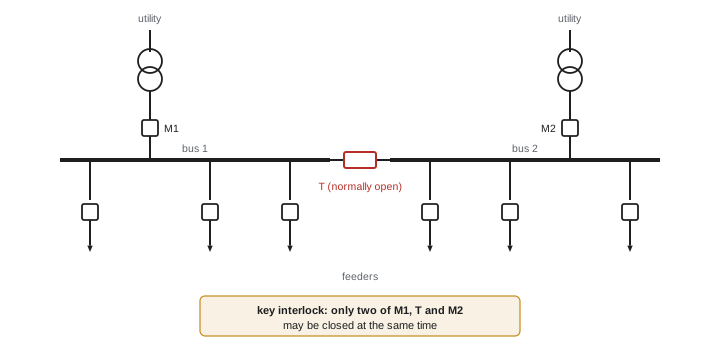
Critical facilities often use a double-ended arrangement: two incoming sources (two utility transformers, or utility and generator), each with a main breaker, feeding two halves of a switchboard joined by a normally open tie breaker. If one source fails, its main opens and the tie closes, so the remaining source supplies both halves (if it has capacity). Automatic transfer schemes use relays and breaker controls to do this. Interlocks prevent dangerous combinations, for example closing the tie while both mains are closed, which would parallel the two sources; mechanical key interlocks (such as Kirk key systems), electrical interlocks and protection relays work together. Electricians testing and operating main-tie-main equipment must understand the sequence and interlocks precisely; incorrect switching can parallel unsynchronized sources or drop critical load.
Motor control centers
An MCC organizes many motor starters and feeders in one assembly, saving space and centralizing control. Each vertical section contains a vertical bus fed from the horizontal main bus, and plug-in units engage the vertical bus with stabs. Units contain a disconnect (circuit breaker or fused switch), contactor, overload relay, control transformer and control devices (ELEC-310), or variable frequency drives, soft starters or feeder breakers. NEMA classifies MCC wiring arrangements: Class I (no interwiring between units) or Class II (interwiring and interlocking between units), and Types A, B and C, describing how field wiring connects (directly to devices, to unit terminal blocks, or to master terminal blocks in each section). Intelligent MCCs include networked overload relays and drives communicating with plant control systems. Withdrawing and inserting energized MCC buckets is a hazardous task with significant arc flash risk; remote racking devices and de-energizing the MCC where practical reduce exposure.
Receiving, setting and installing
Installing a switchboard or switchgear lineup follows a disciplined sequence:
- Receiving: inspect for shipping damage, check the equipment against drawings, store indoors in a clean, dry, heated space if not installed immediately, with space heaters energized if provided.
- Housekeeping pad and floor: the pad must be level and flat within the manufacturer's tolerance, because twisted frames cause misaligned bus splices and binding draw-out mechanisms.
- Setting: move shipping splits with rollers or rigging per the manufacturer's instructions, never by pushing on devices or bus; join sections and bolt frames.
- Bus splices: install splice plates between shipping sections with the specified hardware, torque to the manufacturer's values with a calibrated torque wrench, and mark torqued bolts.
- Anchoring: anchor to the pad as specified, including seismic anchorage where required.
- Cable entry and terminations: route cables through designated areas, support them, maintain bending radius, use lugs rated for the conductor material and size, and torque terminations to the values on the equipment labels.
- Cleaning and inspection: remove debris, tools and packing; vacuum (never blow) dust from bus compartments; check for loose hardware.
- Testing before energization: insulation resistance of bus and cables, breaker settings and trip testing, verification of interlocks, phasing and rotation checks, and continuity of control wiring (Lesson 12).
- Labeling: equipment identification, source, voltage, available fault current where required, and arc flash labels (Lesson 6).
Worked problem
Checking ratings before energization
A new 2,000 A, 480Y/277 V switchboard is labeled with a short-circuit rating of 50 kA and contains main and feeder breakers with 65 kA interrupting ratings. The utility states the maximum available fault current at the service is 42 kA, and the engineer's study shows 47 kA at the switchboard after adding motor contribution. Is the installation acceptable?
Show solution
- The assembly rating (50 kA) must equal or exceed the available fault current at the switchboard: 50 kA ≥ 47 kA.
- Device interrupting ratings (65 kA) also exceed 47 kA.
- The assembly is acceptable today, but with only 3 kA of margin: a future utility transformer upgrade or added motors could exceed the 50 kA rating.
- Record the available fault current on the equipment where required and ask the utility to notify the owner of system changes.
Answer: Acceptable, but with little margin. The lower of the assembly rating and device ratings governs; the assembly's 50 kA rating limits the installation even though the breakers are rated 65 kA. The fault current should be rechecked whenever the supply or large motor loads change.
Operating distribution equipment safely
Operating switches and breakers on energized equipment is routine but not risk-free: an internal fault can be triggered by operation of a device that has deteriorated. Good practice is to stand to the side of the equipment, operate with doors closed and latched, use remote operation where available, wear the PPE specified by the arc flash label or the workplace's risk assessment, and follow switching procedures for complex systems. Before work, equipment is de-energized, locked out and tested for absence of voltage, with attention to all sources, including backfeeds from generators, UPS systems, solar inverters and the other side of tie breakers.
Choosing between distribution equipment types
Choosing the right type of distribution equipment is a balance among cost, space, reliability and maintainability. For a typical office building of moderate size, a front-accessible switchboard with molded-case or insulated-case breakers is economical and compact. For a hospital or data center, where maintenance must be performed without shutting down critical loads and where selective coordination is required, low-voltage switchgear with draw-out power circuit breakers is often specified, despite its higher cost and larger footprint. Industrial plants with many motors use motor control centers to group starters, drives and feeder breakers in one lineup close to the loads.
Space planning for electrical rooms is frequently underestimated in early design. Equipment depth, rear access requirements, working space in front and behind, door swings, and the path for bringing equipment into the room all need attention. A switchgear section that cannot fit through the building's corridors or doors may need to be shipped in smaller splits or delivered before walls are closed. Electricians and foremen who review the electrical room layout early can prevent expensive surprises.
Future flexibility is another consideration. Spaces and spare breakers in switchboards and panelboards allow loads to be added without new equipment. Specifying a few spare sections or prepared spaces in switchgear costs far less during initial construction than adding a new section to energized equipment years later. Many owners require a minimum percentage of spare capacity and spaces in every distribution board for this reason.
Finally, the choice of equipment affects maintenance for its whole life. Draw-out breakers can be removed for testing and replaced with spares quickly; fixed breakers require the bus to be de-energized for replacement. Equipment with infrared windows and remote racking capabilities makes routine maintenance safer. These features should be considered at the design stage, not added afterwards.
Labeling is the last step in installing distribution equipment and one of the most important for the people who will work on it later. Each switchboard, panelboard and feeder breaker should be identified with its name, the source that feeds it, the loads it serves, the available fault current where required, and the arc flash label. Clear, durable labels speed up troubleshooting and lockout, and reduce the chance that someone opens the wrong device.
Common mistakes
MistakeAssuming high breaker interrupting ratings make the assembly suitable.
InsteadCheck the assembly SCCR; the lowest rating governs.
MistakeSetting switchgear on an uneven pad.
InsteadLevel the pad to tolerance to keep bus and draw-out mechanisms aligned.
MistakeTorquing bus splices by feel.
InsteadUse a calibrated torque wrench, the specified values, and mark bolts.
MistakeBlowing dust into bus compartments.
InsteadVacuum and wipe; never blow debris further into equipment.
MistakeOverlooking backfeed sources during lockout.
InsteadIdentify generators, UPS, PV and tie paths before work.
Summary and key terms
- Panelboards, switchboards, LV switchgear, MV switchgear and MCCs serve different levels and duties.
- Equipment is listed to UL 67, UL 891, UL 1558 and UL 845.
- Key ratings are voltage, bus ampacity, SCCR, interrupting rating, short-time withstand and continuous rating.
- Arc-resistant switchgear directs arc energy away from personnel when closed.
- Main-tie-main arrangements need interlocks to prevent paralleling sources.
- MCCs house plug-in starters and drives; racking energized buckets is hazardous.
- Installation requires level pads, torqued splices, clean compartments, testing and labeling.
- Panelboard
- A front-accessible assembly of overcurrent devices in a cabinet.
- Switchboard
- A free-standing assembly of switches, protective devices and buses.
- Low-voltage switchgear
- Metal-enclosed assemblies of draw-out power circuit breakers.
- SCCR
- Short-circuit current rating of an assembly.
- Interrupting rating
- The maximum fault current a device can safely interrupt.
- Short-time withstand
- Current carried for a specified time without damage or tripping.
- 100 %-rated breaker
- A breaker able to carry its full rating continuously in a rated assembly.
- Main-tie-main
- A double-ended arrangement with two mains and a tie breaker.
- Key interlock
- A mechanical key system preventing unsafe switching combinations.
- Motor control center
- An assembly of plug-in motor starter units on a common bus.
Practice problems
Work each problem on paper first, then reveal the answer to check.
What distinguishes LV switchgear from a switchboard?
Show answer
Draw-out power breakers in compartments, barriers, and higher short-time ratings.
Why do short-time withstand ratings matter?
Show answer
They let breakers stay closed during downstream faults for selective coordination.
What load can a standard breaker carry continuously?
Show answer
80 % of its rating.
What does arc-resistant switchgear do?
Show answer
Directs arc gases and energy away from personnel when doors are closed.
What does a two-of-three interlock prevent in a main-tie-main?
Show answer
Paralleling the two sources by closing all three breakers.
What is a NEMA Class II MCC?
Show answer
One with interwiring and interlocking between units.
Why must the housekeeping pad be level?
Show answer
To avoid twisted frames, misaligned bus splices and binding draw-out mechanisms.
An assembly rated 42 kA has 65 kA breakers; available fault current is 45 kA. Acceptable?
Show answer
No; the assembly rating is below the available fault current.
Name four tests before energizing a switchboard.
Show answer
Insulation resistance, breaker settings and trip tests, interlocks, phasing and rotation, control wiring.
Name three backfeed sources to consider during lockout.
Show answer
Generators, UPS systems, solar inverters, tie breakers.
Lesson quiz · 5 questions
Score 60% or more to complete this lesson.
Create a free account to save your progress, take quizzes and earn a certificate.