
ELEC-320 · Lesson 6 of 12 · 25 min
Selective coordination and arc flash hazard
When a fault occurs, the protective device closest to it should open, leaving the rest of the system in service. If instead a main breaker trips for a fault on a branch circuit, a whole building, or a hospital's life safety system, goes dark. This principle is selective coordination. At the same time, the energy released by an arcing fault grows with the time it takes to clear, so the delays that coordination relies on can increase arc flash hazard to workers. Balancing reliability and safety is one of the central problems of power system protection. This lesson explains selective coordination and how it is achieved, where codes require it, arc flash hazard and incident energy, arc flash studies and labels, and the methods used to reduce arc flash energy without sacrificing coordination.
Selective coordination
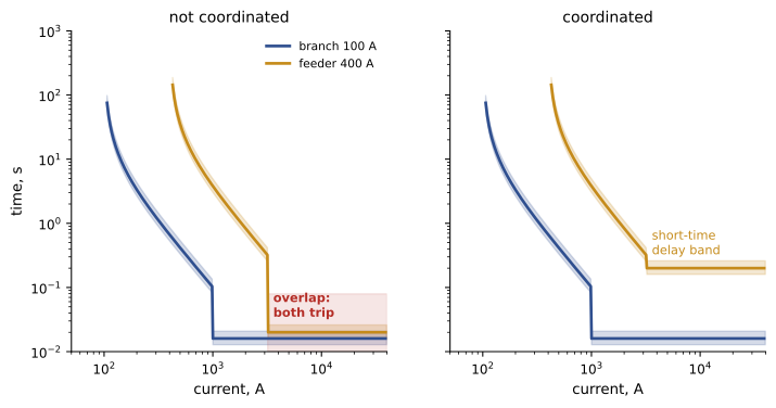
A system is selectively coordinated when, for any overcurrent condition, only the protective device nearest the fault on the supply side opens. Coordination is checked by plotting the time-current curves of devices in series, from the branch breaker up through the feeder and main: for every value of fault current up to the available fault current at the downstream device, the downstream device's total clearing curve must lie below and to the left of the upstream device's minimum trip or melting curve, with no overlap.
Overlap typically occurs in the instantaneous region: two molded-case breakers in series both trip instantaneously above their pickups, so for high faults both may open. Methods to achieve coordination include:
- Using fuses with manufacturers' published selectivity ratios: for example, a Class L fuse upstream will coordinate with a Class J fuse downstream if the ampere ratings are at least a stated ratio, often 2:1.
- Using breakers with short-time delay and no instantaneous (or a high instantaneous) upstream, so the upstream breaker waits for the downstream device to clear; this requires breakers with adequate short-time withstand ratings, such as power circuit breakers.
- Using manufacturers' tested selectivity tables for breaker combinations, which show the fault current up to which specific breakers coordinate, often beyond what curves suggest because of current-limiting effects.
- Zone-selective interlocking (Lesson 4), which allows upstream breakers to trip quickly for faults in their own zone while waiting for downstream devices otherwise.
Where coordination is required
Codes require selective coordination for systems where loss of power endangers life:
In the United States, the NEC requires selective coordination for emergency systems (700.32), legally required standby systems (701.32), critical operations power systems (708.54), elevator circuits with multiple elevators (620.62), and the essential electrical systems of health care facilities (517), in each case for the full range of available fault currents, with limited exceptions. Elsewhere, coordination is a design choice balancing reliability, cost and arc flash.
Data centers and industrial plants often coordinate fully by choice, because unplanned outages are expensive (DCE-450).
Arc flash hazard
An arcing fault in energized equipment creates a plasma at temperatures of thousands of degrees, an intense flash of light and heat, a pressure wave, molten metal and shrapnel. The thermal energy at the worker's position, the incident energy, is measured in calories per square centimeter (cal/cm²); about 1.2 cal/cm² can cause a second-degree burn on bare skin. Arc flash injuries are among the most serious in the electrical trades, and most occur during work on or near energized equipment, such as testing, racking breakers, removing covers, or when tools are dropped.
Incident energy depends on:
- Arcing current, which depends on the available bolted fault current, voltage, electrode configuration and gap.
- Clearing time: how long the upstream protective device takes to clear the arcing fault, often the most important factor; incident energy is roughly proportional to time.
- Working distance: the distance from the arc to the worker's face and chest, typically 455 mm (18 in) for low-voltage panels and 610 mm (24 in) for switchgear; energy falls rapidly with distance.
- Equipment configuration: enclosed boxes focus energy toward the opening; the electrode orientation (vertical, horizontal, in a box or open air) changes the results.
The industry standard method for calculating incident energy is IEEE 1584 (2018 edition), which uses empirical equations based on extensive testing.
Arc flash studies and labels
An arc flash risk assessment, usually by an engineer using study software, models the system (from the utility through every switchboard, panel and MCC), calculates bolted and arcing fault currents, determines the clearing time of the upstream device for each location, and calculates the incident energy and the arc flash boundary, the distance at which incident energy falls to 1.2 cal/cm². Results appear on labels on each piece of equipment.
In the United States, NFPA 70E (Standard for Electrical Safety in the Workplace) requires an arc flash risk assessment and labels showing the nominal voltage, arc flash boundary, and either the available incident energy with working distance or the PPE category, reviewed at least every five years or after major modifications; NEC 110.16 requires field marking of arc flash warnings on equipment, and OSHA enforces employer duties to protect workers.
PPE is selected for the incident energy at the task: arc-rated clothing, face shields or arc flash suit hoods, gloves and hearing protection. Where the incident energy exceeds 40 cal/cm², many organizations do not permit energized work at all, because the pressure wave and other hazards may be lethal regardless of thermal protection.
| Incident energy at working distance | Typical implication |
|---|---|
| Below 1.2 cal/cm² | Arc flash hazard unlikely to cause second-degree burns; normal precautions |
| 1.2 to 4 cal/cm² | Arc-rated clothing and face protection of at least the incident energy |
| 4 to 8 cal/cm² | Arc-rated shirt and pants or coverall, arc-rated face shield and balaclava or hood |
| 8 to 40 cal/cm² | Arc flash suit rated at or above the incident energy; minimize exposure |
| Above 40 cal/cm² | Energized work generally prohibited; de-energize or reduce energy |
Reducing arc flash energy
Because incident energy is roughly proportional to clearing time, the most effective reductions shorten the time to clear an arcing fault, preferably without compromising coordination:
- Energy-reducing maintenance switching: a switch that, while engaged, sets the upstream breaker to a fast instantaneous trip, used while people work on downstream equipment and disengaged afterward. Required in the United States for breakers rated 1,200 A or higher (NEC 240.87) unless another method is used.
- Zone-selective interlocking: upstream breakers trip without intentional delay when the fault is in their zone.
- Differential relaying: compares current entering and leaving a zone (such as a switchboard bus or transformer) and trips instantly for internal faults.
- Arc flash detection relays: optical sensors detect the light of an arc and, combined with an overcurrent check, trip the upstream device within a few milliseconds.
- Current-limiting fuses, which clear high faults in less than half a cycle.
- Lowering available fault current where practical, or splitting large buses.
Other measures reduce exposure rather than energy: remote racking and remote switching, infrared windows for thermography, arc-resistant switchgear, and above all establishing an electrically safe work condition (lockout and verification) instead of working energized.
Worked problem
Effect of a maintenance switch
At a 600 V switchboard bus, the study calculates an arcing fault current of 24 kA. With normal settings, the main breaker's short-time delay clears the arc in 0.5 s, giving 36 cal/cm² at 610 mm. With the maintenance switch engaged, the breaker trips instantaneously in about 0.05 s. Estimate the incident energy with the switch engaged.
Show solution
- Incident energy is approximately proportional to clearing time for the same arcing current and distance.
- Ratio of times: 0.05 ÷ 0.5 = 0.1.
- Estimated energy: 36 × 0.1 = 3.6 cal/cm².
Answer: About 3.6 cal/cm², reducing required PPE from an arc flash suit to arc-rated clothing and face shield. The maintenance switch provides this reduction only while engaged, so procedures must ensure it is turned on before work and off afterward, and its status should be visible.
Coordination versus arc flash
Selective coordination often requires upstream devices to wait, using short-time delays, while arc flash reduction requires them to act fast. Good designs resolve the conflict with tools that distinguish fault locations, such as zone-selective interlocking, differential protection and arc detection, or with temporary measures such as maintenance switches, rather than accepting either poor coordination or high incident energy. Electricians contribute by installing and testing these systems correctly, keeping settings as specified, and reporting changes that affect the study.
Arc flash labels and daily work
Arc flash labels are only useful if workers read them and act on them. Before opening a cover, operating a device or performing a test, a qualified worker should read the label, note the incident energy or PPE category, the arc flash boundary, the shock approach boundaries and the nominal voltage, and confirm that the label date is recent and matches the current system. If the label is missing, damaged, out of date, or inconsistent with the system configuration, the work should be stopped until the hazard is assessed.
Labels depend on assumptions. The incident energy is calculated for a specific working distance, equipment configuration, available fault current and protective device clearing time. If the upstream breaker's settings are changed, if the utility increases its fault current, or if maintenance mode is not enabled when the study assumed it would be, the actual hazard may differ greatly from the label. Changes to the system must therefore trigger a review of the arc flash study, and many standards require the study to be reviewed at least every five years.
Coordination and arc flash studies are best performed together by the same engineer, because a setting that improves one may worsen the other. Electricians support the studies by collecting accurate field data: cable lengths and sizes, conductor material, breaker types and settings, fuse classes and ratings, transformer nameplates and motor data. Inaccurate field data is a leading source of error in these studies.
Arc flash hazard can also be reduced by the way work is planned. Performing tasks with equipment de-energized whenever possible remains the most effective control. When energized work is justified, using remote operation, maintenance mode switches, and the correct PPE for the label's energy level reduces the risk. Training workers to understand what the label means, rather than simply what PPE to wear, builds a stronger safety culture.
Electricians should also understand the limitations of PPE. Arc-rated clothing reduces burn injury from the thermal energy of an arc, but it does not protect against the pressure wave, flying molten metal, or the loud noise that accompany a large arc flash. Above about 40 cal/cm², the pressure and shrapnel hazards are so great that energized work is generally considered unacceptable, and the equipment should be de-energized or the hazard reduced by engineering means before work begins.
When a coordination study shows that full selectivity cannot be achieved with the existing devices, the options include changing settings, replacing breakers with types that have adjustable short-time functions, using fuses with published selectivity ratios, or accepting partial coordination where codes permit it and documenting the decision.
Common mistakes
MistakeAssuming devices coordinate because ratings are larger upstream.
InsteadCheck time-current curves or tested selectivity tables.
MistakeChanging breaker settings without updating the study.
InsteadKeep settings as specified and update studies after changes.
MistakeWorking energized when an electrically safe work condition is possible.
InsteadDe-energize, lock out and verify whenever practicable.
MistakeForgetting to engage or disengage a maintenance switch.
InsteadInclude it in procedures with visible status indication.
MistakeRelying on old arc flash labels.
InsteadReview assessments at least every five years and after modifications.
Summary and key terms
- Selective coordination isolates faults at the nearest device, preserving the rest of the system.
- Coordination is achieved with fuse ratios, short-time delays, tested selectivity tables and ZSI.
- The NEC requires coordination for emergency, legally required standby, COPS, elevator and essential health care systems.
- Arc flash incident energy depends on arcing current, clearing time, distance and configuration, per IEEE 1584.
- NFPA 70E requires arc flash assessments, labels and five-year reviews; NEC 110.16 requires warnings.
- Maintenance switches, ZSI, differential and arc detection relays and current-limiting fuses reduce energy.
- Good designs reconcile coordination and arc flash using zone-based protection.
- Selective coordination
- Only the device nearest a fault on the supply side opens.
- Selectivity ratio
- The fuse rating ratio that ensures coordination.
- Incident energy
- Thermal energy at the working distance from an arc, in cal/cm².
- Arc flash boundary
- The distance at which incident energy falls to 1.2 cal/cm².
- Working distance
- The distance from the arc to the worker's face and chest.
- IEEE 1584
- The standard method for calculating arc flash incident energy.
- Energy-reducing maintenance switching
- A temporary fast-trip setting for work periods.
- Differential protection
- Protection comparing currents into and out of a zone.
- Arc flash relay
- A relay that detects the light of an arc to trip quickly.
- Electrically safe work condition
- Equipment de-energized, locked out and verified.
Practice problems
Work each problem on paper first, then reveal the answer to check.
What is selective coordination?
Show answer
Only the protective device nearest the fault on the supply side opens.
Where do molded-case breaker curves usually overlap?
Show answer
In the instantaneous region.
Name three ways to achieve coordination.
Show answer
Fuse selectivity ratios, short-time delay upstream, tested selectivity tables, ZSI.
What incident energy causes a second-degree burn?
Show answer
About 1.2 cal/cm².
Which factor most often dominates incident energy?
Show answer
Clearing time.
What must an arc flash label show?
Show answer
Nominal voltage, arc flash boundary, and incident energy with working distance or PPE category.
How often must arc flash assessments be reviewed?
Show answer
At least every five years or after major modifications.
If clearing time falls from 0.4 s to 0.08 s, how does incident energy change?
Show answer
It falls to about one-fifth.
How does an arc flash relay detect a fault?
Show answer
By sensing the light of the arc, usually with an overcurrent check.
Why do coordination and arc flash conflict?
Show answer
Coordination uses delays; arc flash reduction needs fast clearing.
Lesson quiz · 5 questions
Score 60% or more to complete this lesson.
Create a free account to save your progress, take quizzes and earn a certificate.