
ELEC-320 · Lesson 4 of 12 · 24 min
Overcurrent protective devices: fuses, breakers and trip units
Overcurrent protective devices are the safety valves of an electrical system. They must carry normal load current indefinitely, ride through harmless transients such as motor starting and transformer inrush, open on sustained overloads before conductors overheat, and interrupt short circuits of tens of thousands of amperes quickly and safely. Large installations use a range of devices, from current-limiting fuses to electronic-trip power circuit breakers with many adjustable settings, and choosing and setting them correctly determines safety, reliability and arc flash energy. This lesson covers how fuses and circuit breakers work, their types and ratings, trip unit functions and settings, series ratings, the rules for protecting conductors including taps, and how to read time-current characteristics.
Overloads and short circuits
Overcurrent takes two forms. An overload is a current moderately above rating, such as 150 % or 300 % of a conductor's ampacity, caused by too much connected load or a stalled motor; it heats conductors gradually, so the protective device can take seconds or minutes to respond. A short circuit or ground fault is a low-impedance fault producing very high current, from several times rating to hundreds of times rating, which must be interrupted in a fraction of a second to limit damage and arc flash. Protective devices therefore have an inverse-time characteristic: the higher the current, the faster they operate.
Fuses
A fuse contains a metal element that melts when current exceeds its rating for long enough, opening the circuit; the arc is extinguished in the fuse body, usually filled with quartz sand. Fuses are simple, reliable, have high interrupting ratings (typically 200 kA or 300 kA for modern low-voltage classes), and do not require maintenance or calibration, though they must be replaced after operating and kept in matched sets.
Current-limiting fuses melt so quickly under high fault currents that they interrupt the current before it reaches its first peak, typically within a quarter cycle, limiting the peak let-through current and the energy (I²t) delivered to downstream equipment. This protects equipment with lower ratings and greatly reduces arc flash energy. Time-delay (dual-element) fuses have a thermal element that tolerates temporary overloads such as motor starting, plus a fast-acting element for short circuits.
Fuse classes define dimensions, ratings and performance so that fuses of lower performance cannot be installed in place of higher ones (rejection features). Common low-voltage classes include Class J (compact, current-limiting, up to 600 A), Class RK1 and RK5 (current-limiting, rejection-type, replacing older Class H), Class L (601 A to 6,000 A, bolt-in), Class T (very compact, fast) and Class CC (small, for control circuits and small motors). Replacing fuses with the correct class and rating is essential: an underrated or slower fuse can turn a cleared fault into an explosion.
Circuit breakers
A circuit breaker is a switch that opens automatically on overcurrent and can be reset. Low-voltage breakers include:
- Molded-case circuit breakers (MCCBs): contacts and trip mechanism in an insulating case, from 15 A to about 3,000 A, with thermal-magnetic trips (a bimetal for overloads and an electromagnet for short circuits) or electronic trip units in larger frames. Most panelboards and many switchboards use MCCBs.
- Insulated-case circuit breakers (ICCBs): larger, two-step stored-energy mechanisms, often draw-out, used in switchboards up to 5,000 A or more, with electronic trip units and some short-time capability.
- Low-voltage power circuit breakers (LVPCBs): heavy-duty, draw-out breakers in switchgear (Lesson 3), designed for maintenance, with high short-time withstand ratings that allow full selective coordination.
Breakers have an interrupting rating (the maximum fault current they can safely interrupt at rated voltage), a continuous current rating (frame and sensor or trip rating), and in power breakers a short-time rating. Unlike fuses, breakers have mechanisms that must be exercised and maintained, and their trip units should be tested periodically (Lesson 12). Their great advantages are resettability, adjustable settings and remote operation.
Electronic trip units and LSIG settings
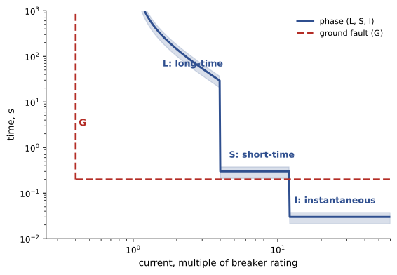
Electronic trip units measure current through sensors and allow the protection curve to be shaped with adjustable functions, commonly abbreviated LSIG:
- Long time (L): the overload protection, with a pickup setting (a multiple of the sensor or plug rating, such as 0.4 to 1.0) and a delay band determining how long it tolerates overloads.
- Short time (S): protection for moderate fault currents, with a pickup (multiple of the long-time setting) and a short delay (for example 0.1 to 0.5 s), optionally with an I²t ramp, allowing downstream devices to clear faults first.
- Instantaneous (I): trips with no intentional delay above a pickup, for high-current faults; may be set high or turned off on power breakers to improve coordination, if short-time protection is provided.
- Ground fault (G): detects current returning by paths other than the circuit conductors, with pickup and delay settings (Lesson 9).
Additional features include zone-selective interlocking (ZSI), in which a downstream breaker that sees a fault signals the upstream breaker to delay, while an upstream breaker that receives no signal trips without delay, and arc energy reduction settings, a maintenance mode that temporarily lowers the instantaneous pickup while people work on energized equipment (Lesson 6). Settings are specified by the engineer's coordination study and must be entered exactly and verified.
Worked problem
Setting a feeder breaker trip unit
A feeder breaker with a 1,600 A sensor protects conductors with an ampacity of 1,280 A (four sets of 400 kcmil at 320 A each, after adjustment). The coordination study specifies long-time pickup 0.8, long-time delay band 10 s at 6 times pickup, short-time pickup 4 times, short-time delay 0.3 s, instantaneous off, ground fault 800 A at 0.2 s. What are the pickup currents?
Show solution
- Long-time pickup: 0.8 × 1,600 = 1,280 A, matching the conductor ampacity.
- Short-time pickup: 4 × 1,280 = 5,120 A, with a 0.3 s delay.
- Instantaneous: off, relying on short-time protection; acceptable only if the breaker's short-time rating covers the available fault current and the engineer accepts the arc flash consequences.
- Ground fault: 800 A pickup, 0.2 s delay.
Answer: Long-time 1,280 A, short-time 5,120 A at 0.3 s, ground fault 800 A at 0.2 s. After entering the settings, record them, photograph the trip unit, and verify them during commissioning with secondary or primary injection testing (Lesson 12).
Series ratings
In a series-rated combination, a downstream breaker with an interrupting rating lower than the available fault current is protected by an upstream device (fuse or breaker) that has been tested together with it, so that the combination can safely interrupt the higher fault current. Series ratings must be tested and listed by the manufacturer for the specific combination; they cannot be engineered by calculation for new installations, and the equipment must be marked. Series ratings save cost, but they compromise selectivity (both devices may trip on a fault) and are restricted where motors contribute significant fault current between the devices. Fully rated systems, in which every device is rated for the available fault current at its location, are preferred where continuity of service matters.
Protecting conductors
The basic rule is that conductors must be protected at their ampacity. Codes allow the next higher standard device rating where the ampacity does not match a standard size, up to a limit (800 A in the NEC; a similar provision in the CEC), above which the device rating must not exceed the ampacity. Exceptions apply to motor circuits (ELEC-310), transformer secondaries, and taps.
Tap rules allow smaller conductors to be connected to a feeder protected at a higher rating, provided they are short, protected from damage, and end in an overcurrent device sized for their ampacity:
In the United States, NEC 240.21 permits feeder taps: the 10-foot tap (ampacity not less than the device it supplies and at least one-tenth of the feeder protection for field installations), the 25-foot tap (ampacity at least one-third of the feeder protection, ending in a single device), transformer taps, and others, each with installation conditions such as enclosure in raceway.
Taps are useful but frequently misapplied; each condition must be met, and the length measured along the actual route.
Reading time-current curves
Every protective device has a time-current characteristic (TCC) curve, plotted on log-log paper with current on the horizontal axis and time on the vertical axis. A fuse curve has a minimum melting curve and a total clearing curve; a breaker curve shows a band between minimum and maximum trip times. To check whether a device protects a conductor or equipment, compare the device curve with the damage curve of the protected item (for example a cable's short-circuit withstand or a transformer's through-fault curve): the device must clear before damage. To check coordination between devices, compare their curves (Lesson 6). Software now plots these curves, but electricians benefit from being able to read them to understand settings and troubleshoot trips.
Replacing and maintaining devices
When replacing fuses or breakers, use the same type, rating, interrupting rating and, for breakers, the same manufacturer's type listed for the panel; mixing breaker brands not classified for a panelboard is not permitted. After a breaker interrupts a high fault, it should be inspected and tested, or replaced, as its contacts and arc chutes may be damaged. Fuses should be replaced as complete sets on three-phase circuits if one has blown and the others may have been stressed. Counterfeit breakers and fuses have been found in supply chains; buy from authorized distributors.
Choosing overcurrent devices in practice
In practice, the choice between fuses and breakers, and among breaker types, is often made by the designer, but electricians must understand the reasoning so that replacements and additions respect it. Replacing a current-limiting fuse with a non-current-limiting type of the same ampere rating can leave downstream equipment exposed to fault currents beyond its rating. Replacing a breaker with one from a different manufacturer, even if it physically fits, may violate the equipment's listing and series ratings. Replacing a trip unit or changing its settings without reference to the coordination study can cause unexpected outages or increased arc flash energy.
When an overcurrent device trips, the cause must be found before it is reset. A thermal trip after a long period suggests overload; an instantaneous trip suggests a short circuit; a ground-fault trip suggests insulation failure or a wiring error. Many electronic trip units record the type of trip and the fault current, which is invaluable for troubleshooting. Repeatedly resetting a breaker onto a fault damages the breaker and the circuit, and may cause an arc flash.
Common mistakes
MistakeReplacing a fuse with any fuse that fits.
InsteadUse the same class, rating and interrupting rating; rejection features exist for a reason.
MistakeEntering trip unit settings without a coordination study.
InsteadUse the engineer's settings, record them and verify by testing.
MistakeEngineering series ratings by calculation for new work.
InsteadUse only tested, listed, marked combinations.
MistakeMeasuring tap length as a straight line.
InsteadMeasure along the actual conductor route and meet every tap condition.
MistakeResetting a breaker after a major fault without inspection.
InsteadInspect, test or replace breakers after high-current interruptions.
Summary and key terms
- Overloads are moderate and slow; short circuits are severe and must clear in a fraction of a second.
- Fuses are simple, high-interrupting and, when current-limiting, reduce let-through energy.
- Fuse classes such as J, RK1, RK5, L, T and CC have rejection features for correct replacement.
- MCCBs, ICCBs and LVPCBs differ in size, construction, short-time capability and maintenance.
- LSIG trip settings shape protection; ZSI and maintenance modes reduce fault energy.
- Series ratings must be tested and listed; fully rated systems give better selectivity.
- Conductors are protected at ampacity with next-size-up and tap rules applied carefully.
- Overload
- A moderate overcurrent from excessive load.
- Short circuit
- A low-impedance fault producing very high current.
- Current-limiting fuse
- A fuse that interrupts fault current before its first peak.
- Let-through energy (I²t)
- The energy passed by a device during a fault.
- Rejection feature
- A physical feature preventing installation of the wrong fuse class.
- MCCB
- Molded-case circuit breaker.
- LSIG
- Long-time, short-time, instantaneous and ground-fault trip functions.
- Zone-selective interlocking
- Communication between breakers to speed tripping for faults in their zone.
- Series rating
- A tested combination allowing a lower-rated downstream device.
- Tap conductor
- A conductor connected to a feeder without protection at the connection point.
Practice problems
Work each problem on paper first, then reveal the answer to check.
Why do protective devices have inverse-time characteristics?
Show answer
To tolerate brief overloads while clearing high faults quickly.
What does a current-limiting fuse do?
Show answer
Interrupts fault current before its first peak, limiting let-through energy.
Which fuse class covers 601 A to 6,000 A?
Show answer
Class L.
What are the four LSIG functions?
Show answer
Long time, short time, instantaneous, ground fault.
A 2,000 A sensor has long-time pickup 0.7. What is the pickup current?
Show answer
1,400 A.
With short-time pickup 5 times and long-time pickup 1,400 A, what is the short-time pickup?
Show answer
7,000 A.
How does zone-selective interlocking work?
Show answer
A downstream breaker seeing a fault restrains the upstream breaker; without a restraint signal, the upstream breaker trips quickly.
Why are series ratings poor for continuity of service?
Show answer
Both devices may trip on a fault, losing selectivity.
What must a TCC comparison show for equipment protection?
Show answer
The device clears before the equipment damage curve is reached.
Why replace all three fuses on a three-phase circuit after one blows?
Show answer
The others may have been stressed and weakened.
Lesson quiz · 5 questions
Score 60% or more to complete this lesson.
Create a free account to save your progress, take quizzes and earn a certificate.