
ELEC-320 · Lesson 2 of 12 · 25 min
Large services and load calculations
The service is where the utility's system ends and the building's begins. For a large building, it involves a utility transformer or a customer-owned substation, metering with current transformers, service conductors carrying thousands of amperes, and service equipment that can isolate and protect the whole installation. Planning a service starts years before installation, with load calculations that determine its size and discussions with the utility about supply arrangements. This lesson covers how large services are supplied, the code rules for services, calculating the service load, sizing service conductors including parallel sets, metering, and coordination with the utility.
How large services are supplied
Large buildings are supplied in several ways, depending on load and utility practice:
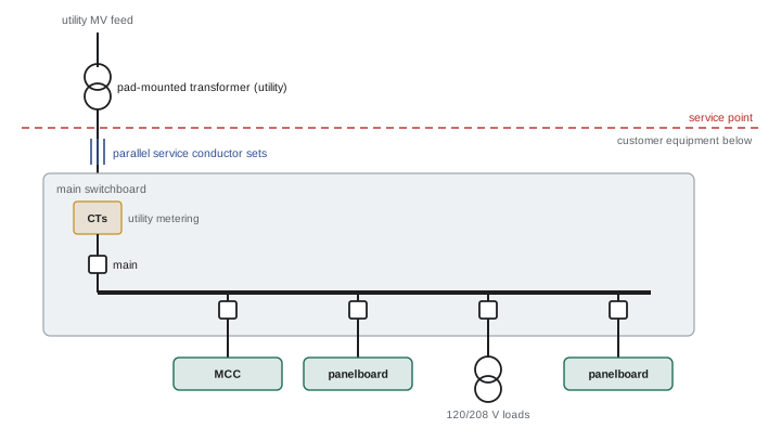
- Secondary service from a utility pad-mounted transformer: the utility owns the transformer, usually on a pad outside the building or in a vault, and supplies low voltage (120/208 V, 347/600 V or 480Y/277 V) to the customer's service equipment. Common up to a few megavolt-amperes.
- Utility transformer vault inside the building, with the utility supplying medium voltage to its own transformers and low voltage to the customer.
- Primary (medium-voltage) service: the customer takes supply at medium voltage (for example 4.16 kV to 34.5 kV), owns its own switchgear and transformers, and often receives a lower tariff. Common for large industrial plants, campuses, hospitals and data centers (Lesson 11).
- Multiple services or dual feeds for large or critical buildings, where permitted, to provide capacity or redundancy.
The arrangement determines who owns and maintains which equipment, where the service point (the demarcation between utility and customer) is, and what the electrician installs.
Code rules for services
In the United States, NEC Article 230 governs services. Generally, a building is supplied by only one service, with exceptions for fire pumps, emergency and standby systems, parallel power production, multiple-occupancy buildings, capacity requirements (loads over 2,000 A at 600 V or less, or where a single service cannot supply the load) and different characteristics. The service disconnecting means must be at a readily accessible location nearest the point of entrance of the service conductors; a service may have up to six disconnects grouped together, each in a separate enclosure or section under recent editions. Services of 1,000 A or more on solidly grounded wye systems of more than 150 V to ground require ground-fault protection of equipment (Lesson 9), and recent editions require surge protection on services supplying dwelling units and emergency systems. Utility requirements (each utility's service rules or "blue book") apply alongside the code.
Service conductors have no overcurrent protection on their supply side except the utility's transformer fuses, so codes require them to be kept outside the building or enclosed in concrete or masonry until they reach the service equipment, limiting the risk of a fault inside the building on unprotected conductors.
Calculating the service load
The service must be large enough for the calculated load, which is not simply the sum of all connected loads, because not everything operates at full load at the same time. Codes provide methods:
- NEC Article 220 provides calculation methods: general lighting loads by occupancy in volt-amperes per square foot (Table 220.12, for example 1.3 VA/ft² for offices in the 2023 edition), receptacle loads with demand factors, motor loads at 125 % of the largest motor plus the others (Article 430), heating and air conditioning (the larger of the two when not used together, 220.60), kitchen equipment and other loads with their demand factors. Continuous loads are sized at 125 % for conductors and overcurrent devices unless equipment is listed for 100 % continuous operation. Section 220.87 permits using the maximum demand of an existing installation, measured over a year or a 30-day recording, to size additions.
Designers also consider future growth, typically adding 20 % to 25 % spare capacity, and the characteristics of the load, such as motor starting, harmonics and power factor. For data centers and other facilities with continuous, well-defined loads, the calculation is often based on the IT load and mechanical systems rather than per-area values (DCE-210).
Sizing service conductors
Large services use conductors in parallel, with several sets of identical cables in separate raceways, because single conductors larger than about 500 to 750 kcmil are hard to pull and terminate, and because parallel sets in separate raceways reduce heating. Codes permit paralleling of conductors of size 1/0 AWG and larger, provided that, in each phase, neutral and bonding group, the conductors are the same length, the same material, the same size, have the same insulation type, and are terminated in the same manner, and that each raceway or cable contains one conductor of each phase and the neutral, so that magnetic fields cancel and currents divide equally. Ampacity correction for ambient temperature and adjustment for the number of current-carrying conductors in a raceway apply, and terminations (usually rated 75 °C) limit the usable ampacity.
Worked problem
Sizing a large service
After applying the NEC demand factors, a commercial building's calculated load is 820 kVA at 480Y/277 V. Select the service rating and copper service conductors (75 °C terminations, one set per raceway).
Show solution
- Current: 820,000 ÷ (1.732 × 480) = 986 A.
- Allowing for continuous loads at 125 % and growth, select a 1,600 A service (986 × 1.25 = 1,233 A).
- Conductors: 4 sets of 500 kcmil copper at 380 A each = 1,520 A is too small; 5 sets of 400 kcmil at 335 A = 1,675 A, or 4 sets of 600 kcmil at 420 A = 1,680 A.
- Neutral: size for the maximum unbalanced load and harmonics; with many non-linear loads, consider a full-size or oversized neutral.
Answer: A 1,600 A service with five parallel sets of 400 kcmil copper or four of 600 kcmil, each set in its own conduit with the neutral. Because the service exceeds 1,000 A on a 480Y/277 V system, ground-fault protection is required.
Metering
Services above about 200 A are usually metered with current transformers (CTs), because the meter cannot carry full load current directly. The utility specifies the metering arrangement: a CT compartment in the switchboard (a utility metering section with sealed access), or a separate CT cabinet, with test switches, a meter socket, and secondary wiring of specified size and length. CT secondaries must never be open-circuited while the primary carries current, because the open secondary can develop dangerously high voltage; test switches short the secondaries before the meter is removed. At primary services, metering uses both CTs and voltage transformers at medium voltage. Customers increasingly install their own power meters on mains and feeders for energy management, power quality monitoring and load data for future planning.
Coordinating with the utility
Large services require early and continuing coordination with the utility:
- Service application: load information (connected and calculated load, largest motors, special loads such as EV chargers and drives), requested in-service date, and site plan.
- Utility design: transformer size and location, primary cable route, metering, and the customer's responsibilities (pads, ducts, vaults, grounding, clearances).
- Available fault current: the utility provides the maximum available short-circuit current at the service, needed for equipment ratings and arc flash studies (Lessons 5 and 6). It should be requested in writing and updated if the utility changes its system.
- Construction coordination: civil works, duct banks, transformer delivery and energization dates.
- Inspection and connection authorization: the utility connects only after the electrical inspection authority approves the installation.
Utility lead times for large services can be long, especially where system upgrades are needed, so service applications should be made as early as possible (DCE-470).
Working space around large equipment
Service equipment and switchboards require working space for safe operation and maintenance:
The NEC (110.26) requires working space in front of equipment of at least 3 ft, 3.5 ft or 4 ft deep depending on voltage and conditions, at least 30 in wide, and with headroom of 6.5 ft or the height of the equipment. For equipment rated 1,200 A or more and over 6 ft wide containing overcurrent devices or switching devices, there must be an entrance at each end of the working space (with exceptions), and doors within 25 ft of the working space must open outward with listed panic hardware.
Working space must not be used for storage, and dedicated space above and below equipment must be kept free of foreign piping and ducts.
Planning a large service from start to finish
A large service is a project in its own right, often taking many months from the first utility application to energization. The typical sequence starts with a preliminary load estimate from the designer, which is submitted to the utility with a request for service. The utility responds with its requirements: the supply voltage, the transformer arrangement, the location of the point of connection, metering requirements, the available fault current, and any costs the owner must pay for line extensions or transformers. The designer then completes the detailed load calculation and the single-line diagram, and the switchboard or switchgear is ordered, frequently with lead times of many months for large equipment.
While the equipment is being built, the electrical contractor installs the underground ducts, concrete pads, grounding electrodes and service raceways. Shop drawings for the service equipment are reviewed by the designer and often by the utility, which must approve the metering compartment and the arrangement of its current transformers. Inspections by the authority having jurisdiction occur at several stages, such as before backfilling underground duct banks and before energization.
Coordination problems on large services commonly come from late changes. A tenant adds a large load, the owner decides to include electric vehicle charging, or the utility revises its transformer size and available fault current. Each change can ripple through the load calculation, the service rating, equipment interrupting ratings and the coordination and arc flash studies. A good practice is to keep a load and change log from the start of the project, so that every change is captured and its effects checked before equipment is released for manufacture.
After energization, the service drawings, load calculation and utility correspondence should be handed over to the owner with the rest of the project records. Future additions will depend on knowing how much spare capacity the service actually has, and the measured demand from the utility meter over the first year gives a far better picture than the original calculation.
Temporary power is another early consideration on large projects. Construction sites need power long before the permanent service is energized, and the temporary service must be planned, permitted and inspected in its own right. Its location should avoid conflict with the permanent electrical room, underground ducts and site traffic, and its capacity should cover cranes, hoists, welders, site trailers and temporary heating. Planning the change-over from temporary to permanent power avoids extended outages for the trades still working in the building.
Common mistakes
MistakeAdding connected loads without demand factors.
InsteadUse the code calculation methods and demand factors, plus growth allowance.
MistakeParalleling conductors of different lengths or materials.
InsteadKeep paralleled conductors identical and each raceway with all phases and neutral.
MistakeOpening CT secondaries under load.
InsteadShort CT secondaries with test switches before removing the meter.
MistakeAssuming the available fault current without asking the utility.
InsteadObtain the available fault current in writing for equipment ratings and studies.
MistakeUsing working space for storage.
InsteadKeep required working space and exits clear.
Summary and key terms
- Large services are supplied from utility pad-mounted transformers, vaults or customer-owned medium-voltage substations.
- NEC Article 230 governs services; one service with exceptions; up to six grouped disconnects; GFP at 1,000 A and above.
- Service loads are calculated with code methods, demand factors, continuous load rules and growth allowances.
- Parallel conductors must be identical and grouped with all phases and neutral in each raceway.
- CT metering arrangements follow utility specifications; never open CT secondaries under load.
- Utility coordination covers applications, design, fault current, construction and inspection.
- Large equipment needs working space, headroom and multiple exits.
- Service
- The conductors and equipment delivering utility power to a building.
- Service point
- The demarcation between utility and customer facilities.
- Primary service
- Supply taken at medium voltage with customer-owned transformers.
- Calculated load
- The load determined using code methods and demand factors.
- Demand factor
- The ratio of maximum demand to connected load.
- Parallel conductors
- Two or more conductors connected to act as one.
- Current transformer
- A transformer reducing current for metering or protection.
- Available fault current
- The maximum short-circuit current at a point in the system.
- Working space
- Clear space required in front of electrical equipment.
- Conditions of service
- A utility's requirements for customer connections.
Practice problems
Work each problem on paper first, then reveal the answer to check.
Name three ways large buildings receive service.
Show answer
Utility pad-mounted transformer, utility vault, primary (medium-voltage) service, multiple services.
Why must service conductors be kept outside or encased until they reach the service equipment?
Show answer
They have no overcurrent protection on their supply side except utility fuses.
What is a demand factor?
Show answer
The ratio of maximum demand to connected load.
What growth allowance is typical in service design?
Show answer
About 20 % to 25 %.
What is the minimum size for parallel conductors?
Show answer
1/0 AWG.
Why must each raceway contain all phases and the neutral of a parallel set?
Show answer
So magnetic fields cancel and currents divide equally, avoiding heating.
How many sets of 500 kcmil copper (380 A at 75 °C) are needed for 1,400 A?
Show answer
Four sets (1,520 A).
Why should CT secondaries never be opened under load?
Show answer
Dangerously high voltages can develop.
What information about the service must come from the utility in writing?
Show answer
The maximum available fault current.
What extra exit requirement applies to large equipment?
Show answer
Access or entrances at both ends of the working space, with outward-opening doors and panic hardware.
Lesson quiz · 5 questions
Score 60% or more to complete this lesson.
Create a free account to save your progress, take quizzes and earn a certificate.