
ELEC-320 · Lesson 7 of 12 · 24 min
Transformers in distribution systems
Transformers connect the voltage levels of a distribution system: utility transformers step medium voltage down to the service voltage, and building transformers step the main distribution voltage down to the 120 V systems used for receptacles and small loads. Large facilities may have dozens or hundreds of transformers, from pad-mounted units of several megavolt-amperes to small dry-type units in electrical rooms. Electricians select, install, connect, ground, protect and test them. This lesson builds on the transformer theory of ELEC-210 with the practical knowledge needed for distribution work: transformer types and ratings, efficiency standards, connections and phase shift, taps, inrush, overcurrent protection, grounding of separately derived systems, installation requirements, harmonics and K-rated units, and testing.
Types of transformers
- Ventilated dry-type transformers: windings insulated with high-temperature materials and cooled by air, used indoors for building distribution, typically from 15 kVA to 2,500 kVA. They are the common 600-120/208 V or 480-208Y/120 V units in electrical rooms.
- Cast-resin dry-type transformers: windings encapsulated in epoxy, resistant to moisture and contamination, used for larger indoor and harsh-environment applications, including medium-voltage unit substations.
- Liquid-filled transformers: windings immersed in mineral oil or less-flammable fluids such as natural esters, which provide better cooling and longer life; used outdoors as pad-mounted and substation transformers, and indoors only under strict conditions (vaults or listed less-flammable fluids with clearances).
- Pad-mounted transformers: tamper-resistant, liquid-filled units in a locked cabinet on a concrete pad, used by utilities and in customer-owned medium-voltage systems.
- Unit substations: a medium-voltage switch or breaker, transformer and low-voltage switchgear assembled as one lineup.
- Special transformers: control power transformers, isolation transformers, autotransformers (including buck-boost), and drive isolation transformers.
Ratings
The nameplate of a distribution transformer shows its kVA rating, primary and secondary voltages and connections, frequency, percent impedance, temperature rise, basic impulse level (BIL), taps, weight and wiring diagram. Temperature rise ratings for dry-type units (commonly 150 °C, 115 °C or 80 °C above a 40 °C ambient, with 220 °C insulation) indicate how hot the windings run at full load: lower-rise units run cooler, are more efficient at high loads, and have more overload capacity. Liquid-filled units typically have 65 °C rise ratings and may have fan-cooled ratings that increase capacity. Percent impedance determines fault current (Lesson 5) and voltage regulation: higher impedance reduces fault current but increases voltage drop under load.
In the United States, the Department of Energy sets minimum efficiency standards for distribution transformers under 10 CFR Part 431, with levels raised in 2016 and new standards adopted in 2024 that take effect in 2029; dry-type transformers are listed to UL 1561 or UL 1562.
Connections and phase shift
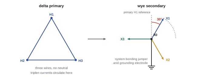
The most common building transformer connection is delta primary, wye secondary (delta-wye). The delta primary needs only three wires and traps triplen harmonic currents circulating within the delta, while the wye secondary provides a neutral for line-to-neutral loads and a point for system grounding. A delta-wye transformer shifts the phase of the secondary voltages by 30° relative to the primary, which matters when paralleling transformers or connecting sources: transformers connected in parallel must have the same voltage ratio, the same phase shift (vector group, such as Dyn1 or Dyn11), similar percent impedance, and the same phase rotation, or large circulating currents will flow. Wye-wye connections are used in some utility systems but require care with neutrals and harmonics; delta-delta connections have no neutral and are used for some three-wire industrial loads.
Taps
Most distribution transformers have primary taps to compensate for supply voltage that differs from nominal, commonly two taps above and four below nominal in 2.5 % steps (written as 2 × 2.5 % FCAN and 4 × 2.5 % FCBN, full-capacity above and below normal). If the supply voltage is consistently high, connecting to a higher primary tap lowers the secondary voltage, and vice versa. For example, if a 600 V primary actually measures 624 V (4 % high), the secondary of a 600-208 V transformer on the nominal tap would be about 216 V; moving to the +5 % tap (630 V) brings it back to about 206 V. Taps are changed only with the transformer de-energized and locked out, and all phases must be set to the same tap.
Inrush current
When a transformer is energized, its core may saturate briefly, drawing an inrush current of typically 8 to 12 times rated current (sometimes more for small units) for about a tenth of a second, depending on the point on the voltage wave and the residual magnetism in the core. Protective devices on the primary must ride through this inrush; this is why codes allow primary overcurrent devices well above rated current, and why instantaneous settings on transformer feeder breakers must be above the inrush peak. Energizing several large transformers at once can trip upstream devices or dip the voltage, so large facilities may energize them in sequence.
Overcurrent protection
Transformers must be protected against overload and faults, and their primary and secondary conductors must be protected according to the code rules for each.
In the United States, NEC 450.3(B) permits primary-only protection of transformers rated 1,000 V or less at not more than 125 % of rated primary current (with next-size-up rules), or primary protection up to 250 % where the secondary is protected at not more than 125 % of rated secondary current. Secondary conductors must be protected under 240.21(C), which allows unprotected secondary conductors up to 10 ft or 25 ft long (and longer in some industrial installations) if they terminate in an overcurrent device rated for their ampacity, and 240.4(F) allows two-wire and delta-delta three-wire secondaries to be protected by the primary device in some cases.
Worked problem
Protecting a building transformer
A 75 kVA, 480 V delta to 208Y/120 V dry-type transformer feeds a panelboard. Calculate the rated currents and propose primary and secondary protection using NEC 450.3(B).
Show solution
- Primary current: 75,000 ÷ (1.732 × 480) = 90 A. Secondary current: 75,000 ÷ (1.732 × 208) = 208 A.
- Secondary protection at not more than 125 %: 1.25 × 208 = 260 A; a 225 A or 250 A main breaker in the panel, with secondary conductors sized for it.
- Primary protection at not more than 250 %: up to 225 A, but in practice a 125 A breaker (139 %) rides through inrush and allows smaller primary conductors.
- Check that the primary breaker's instantaneous trip is above the transformer inrush (8 to 12 times 72 or 90 A), and that the devices coordinate with each other.
Answer: Primary 125 A and secondary main 225 A or 250 A, with conductors sized accordingly. The 10-ft or 25-ft secondary conductor rules apply to the run from transformer to panel.
Grounding separately derived systems
A transformer with no direct electrical connection between primary and secondary circuit conductors creates a new, separately derived system, which must be grounded (if it is a grounded system) at the transformer or at the first disconnecting means, but not both:
- A system bonding jumper connects the secondary neutral (X0) to the equipment bonding or grounding conductor and enclosure at one point only.
- A grounding electrode conductor connects that point to the nearest suitable grounding electrode, typically building structural steel or a water pipe electrode that is part of the building's grounding electrode system (Lesson 8).
- A supply-side bonding jumper connects the transformer enclosure to the first disconnect enclosure where the bonding point is not in the transformer.
Making the neutral-to-ground connection at more than one point creates parallel paths for neutral current on bonding conductors, conduits and building steel, which causes stray currents, electromagnetic interference, and nuisance tripping of ground-fault protection. Verifying a single bonding point is an important commissioning check.
Installation requirements
Transformers must be installed with the ventilation clearances specified on the nameplate (typically 150 mm or 6 in from walls for ventilated dry-types), away from combustible materials, accessible for inspection, and protected from physical damage. Dry-type transformers above specified sizes must be in rooms of fire-resistant construction or separated from combustibles; liquid-filled transformers indoors generally require vaults unless they use listed less-flammable fluids and meet specified conditions. Transformers produce audible hum (sound levels are listed in decibels by size), so locating them away from occupied quiet spaces and using vibration isolation pads and flexible conduit connections reduces noise transmission. Seismic anchoring may be required.
Harmonics and K-rated transformers
Non-linear loads cause harmonic currents that increase transformer losses, especially eddy current losses in the windings, which rise with the square of frequency. Triplen harmonics from line-to-neutral loads circulate in the delta primary, adding heating. A standard transformer serving a heavily non-linear load may overheat at well below its nameplate rating. K-rated transformers (K-4, K-13, K-20) are designed with lower eddy losses, larger neutrals (often 200 %) and electrostatic shields to serve such loads; harmonic mitigating transformers with phase-shifting windings cancel some harmonics. Alternatively, a standard transformer can be derated according to the measured harmonic spectrum (ELEC-210).
Testing transformers
Before energizing a new or repaired transformer, and during maintenance, typical tests include: insulation resistance of each winding to ground and between windings; turns ratio (TTR) on every tap, confirming the ratio within 0.5 % of nameplate and the correct phase relationship; winding resistance, comparing phases; verification of tap settings on all phases, the system bonding jumper and grounding connections; inspection of connections and torque; and, for liquid-filled units, oil level, leaks and oil sampling for dissolved gas analysis. After energization, verify secondary voltages and phase rotation, then monitor temperature and load (Lesson 12).
Transformer problems in the field
Common transformer problems found by electricians include overheating from overloading or harmonic loads, high or low secondary voltage from incorrect taps, noisy operation from loose mounting or inadequate isolation, and failed windings from moisture or contamination. Thermal scans of transformer connections and enclosures, checks of secondary voltages under load, and measurements of neutral current help identify these problems early. Ventilation openings blocked by stored materials are a frequent and easily corrected cause of overheating.
Replacing a failed transformer is an opportunity to correct earlier problems. The replacement may need a different temperature rise rating, a K-rating for harmonic loads, a higher efficiency level to meet current regulations, or a lower sound level for its location. Before installation, verify the nameplate voltages, connections, impedance and tap arrangement against the drawings and the old unit, since a change in impedance will change the available fault current and may affect downstream equipment ratings and the arc flash study.
Common mistakes
MistakeParalleling transformers with different phase shifts.
InsteadMatch ratio, vector group, impedance and rotation before paralleling.
MistakeChanging taps on an energized transformer or on one phase only.
InsteadDe-energize, lock out, and set all phases to the same tap.
MistakeSetting primary instantaneous trips below inrush.
InsteadSet above inrush current and verify with the coordination study.
MistakeBonding neutral to ground at both the transformer and the panel.
InsteadBond at one point only for each separately derived system.
MistakeLoading standard transformers fully with non-linear loads.
InsteadUse K-rated or harmonic mitigating units, or derate.
Summary and key terms
- Distribution transformers include ventilated and cast-resin dry-types, liquid-filled, pad-mounted and unit substations.
- Ratings include kVA, voltages, impedance, temperature rise, BIL and taps; efficiency is regulated.
- Delta-wye connections provide a neutral, trap triplens and shift phase by 30°.
- Taps in 2.5 % steps correct for supply voltage; change them de-energized on all phases.
- Inrush of 8 to 12 times rated current must be tolerated by primary protection.
- NEC 450.3(B) sets 125 % primary-only or 250 %/125 % primary and secondary protection; 240.21(C) governs secondary conductors.
- Separately derived systems are bonded at one point with a grounding electrode conductor; K-rated units and testing complete the picture.
- Dry-type transformer
- A transformer cooled by air without liquid.
- Temperature rise
- Winding temperature above ambient at full load.
- Delta-wye
- A transformer with delta primary and wye secondary.
- Vector group
- A code describing winding connections and phase shift.
- Tap
- A winding connection that adjusts the turns ratio.
- Inrush current
- The brief high current when energizing a transformer.
- Separately derived system
- A system with no direct connection to the supply circuit conductors.
- System bonding jumper
- The connection between neutral and equipment bonding at a separately derived system.
- K-factor
- A rating for a transformer's ability to serve harmonic loads.
- Turns ratio test
- A test confirming a transformer's voltage ratio and phase relationship.
Practice problems
Work each problem on paper first, then reveal the answer to check.
Why are delta-wye transformers common in buildings?
Show answer
They provide a neutral, trap triplen harmonics in the delta, and need only three primary wires.
What phase shift does a delta-wye transformer introduce?
Show answer
30°.
Name four conditions for paralleling transformers.
Show answer
Same ratio, same phase shift, similar impedance, same rotation.
A 600 V primary measures 585 V. Which tap direction raises the secondary?
Show answer
A lower primary tap (for example −2.5 %).
What is typical transformer inrush?
Show answer
8 to 12 times rated current for about 0.1 s.
What are the rated currents of a 150 kVA, 480-208 V transformer?
Show answer
Primary 180 A, secondary 416 A.
What does the system bonding jumper do?
Show answer
Connects the neutral to the bonding system at one point.
What happens if neutral and ground are bonded at two points?
Show answer
Neutral current flows on bonding paths, causing stray currents and nuisance GFP trips.
Why are K-rated transformers used?
Show answer
To serve non-linear loads without overheating.
Name four transformer tests before energization.
Show answer
Insulation resistance, turns ratio, winding resistance, tap and grounding verification, connection inspection.
Lesson quiz · 5 questions
Score 60% or more to complete this lesson.
Create a free account to save your progress, take quizzes and earn a certificate.