
ELEC-210 · Lesson 9 of 12 · 33 min
Three-phase transformer connections, banks and testing
Lesson 8 introduced transformers and listed the common three-phase connections. In the field, electricians build three-phase banks from single-phase units, connect and phase-check new transformers, parallel transformers, keep a system running on an open delta when one unit fails, provide a ground reference on an ungrounded system, and test transformers before energizing them. Each task depends on understanding how voltages and currents relate in each winding connection. This lesson works through those relationships, the 30° phase shift, building banks with correct polarity, open-delta operation, paralleling conditions and load sharing, grounding transformers, sizing, and the acceptance tests performed before energization.
Voltages and currents in each connection
In a wye winding, each coil is connected between a line and the neutral, so the coil voltage is the line-to-neutral voltage, \(V_{\text{line}}/\sqrt3\), and the coil current equals the line current. In a delta winding, each coil is connected between two lines, so the coil voltage equals the line voltage, and the coil current is \(I_{\text{line}}/\sqrt3\) for balanced loads (Lesson 6).
When single-phase transformers form a three-phase bank, each unit's rating and voltages must suit its position:
| Bank (primary-secondary) | Primary coil voltage | Secondary coil voltage | Overall line voltage ratio |
|---|---|---|---|
| Delta-delta | \(V_P\) | \(V_S\) | \(V_P/V_S = a\) (coil ratio) |
| Delta-wye | \(V_P\) | \(V_S/\sqrt3\) | \(a/\sqrt3\) |
| Wye-delta | \(V_P/\sqrt3\) | \(V_S\) | \(\sqrt3\,a\) |
| Wye-wye | \(V_P/\sqrt3\) | \(V_S/\sqrt3\) | \(a\) |
Worked problem
Building a 480 V to 120/208 V bank
Three single-phase transformers are to form a delta-wye bank from a 480 V supply to a 120/208 V secondary, for a 150 kVA load. What coil voltages and kVA rating does each unit need, and what are the coil currents at full load?
Show solution
- Primary coils in delta: 480 V each. Secondary coils in wye: \(208/\sqrt3 = 120\) V each. Each unit: 480-120 V, \(150/3 = 50\) kVA.
- Secondary coil current = line current: \(150{,}000/(\sqrt3 \times 208) = 416\) A.
- Primary line current: \(150{,}000/(\sqrt3 \times 480) = 180\) A; primary coil current: \(180/\sqrt3 = 104\) A (check: \(50{,}000/480 = 104\) A).
Answer: Three 50 kVA units rated 480-120 V. Each secondary coil carries 416 A and each primary coil 104 A, while the primary lines carry 180 A.
The 30° phase shift
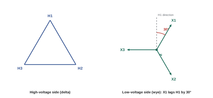
Delta-wye and wye-delta connections shift the secondary voltages by 30° relative to the primary, because a delta coil voltage is a line-to-line voltage while a wye coil voltage is a line-to-neutral voltage, and these are 30° apart. North American standards (ANSI) specify that for delta-wye and wye-delta transformers, the high-voltage side leads the low-voltage side by 30°. Delta-delta and wye-wye connections produce no shift.
The shift does not matter to the loads, which see a normal three-phase supply, but it matters whenever two sources are connected together: two transformers can be paralleled, or a load transferred between two sources without interruption, only if their secondaries have the same phase shift relative to a common primary. A delta-wye transformer cannot be paralleled with a delta-delta transformer, even with identical voltages, because their secondaries are 30° apart: connecting them would create a large circulating current, effectively a short circuit through a voltage difference of about \(2\sin 15° = 52\%\) of rated voltage.
Building a bank: polarity and connections
Single-phase transformer terminals are marked H1, H2 (high voltage) and X1, X2 (low voltage). H1 and X1 have the same instantaneous polarity. In a subtractive polarity transformer (standard for larger units and higher voltages), H1 and X1 are physically opposite each other; in an additive polarity transformer (common for small distribution units), they are diagonally opposite. Polarity can be checked with a simple test: connect H1 to the adjacent low-voltage terminal, apply a low voltage to the high-voltage winding, and measure between H2 and the other low-voltage terminal; a reading less than the applied voltage indicates subtractive polarity, more indicates additive.
Connecting a bank with one unit reversed produces wrong voltages. In a wye secondary, a reversed coil puts its voltage 180° out of position, so two of the line-to-line voltages read only about 120 V instead of 208 V. In a delta secondary, a reversed coil makes the voltage around the closed delta twice the coil voltage instead of zero, causing a large circulating current when the delta is closed. The standard practice before closing a delta is to leave one corner open and measure across the opening: it should read zero (or near zero); a reading of twice the coil voltage means one coil is reversed.
Worked problem
Checking a delta before closing it
A delta-delta bank of three 240 V secondary coils is connected with the last corner open. The voltage measured across the opening is 480 V. What does this mean?
Show solution
- Correctly connected, the three coil voltages sum to zero around the delta.
- A reading of twice the coil voltage (480 V) means one coil is reversed: its voltage adds instead of canceling.
Answer: One coil is reversed. Closing the delta would short-circuit a 480 V source through the low impedance of the windings, causing a very large circulating current. Reverse the leads of the offending coil (identified by measuring with each coil reversed in turn) and recheck for zero before closing.
Open-delta operation
A delta-delta bank can keep supplying three-phase power with only two transformers, connected in open delta (V-V). This is used to keep a load running when one unit fails, and for new installations expecting future growth, where the third unit is added later. Because the two remaining transformers carry line current rather than coil current (now \(\sqrt3\) times larger relative to their rating), the bank capacity is reduced:
Worked problem
Capacity of an open delta
A delta-delta bank of three 100 kVA transformers loses one unit. What load can the remaining two carry? What is the utilization of the installed transformer capacity?
Show solution
- Open-delta capacity: \(\sqrt3 \times 100 = 173\) kVA (57.7% of 300 kVA).
- Installed capacity in service: 200 kVA, of which 173 kVA is usable: 86.6%.
Answer: 173 kVA. The load must be reduced to this or the remaining units will overheat. Open-delta banks also produce slightly unbalanced voltages under load, which affects motors (Lesson 6).
Paralleling transformers
Paralleling transformers, connecting their primaries to the same supply and their secondaries to the same bus, increases capacity or provides redundancy. Conditions for satisfactory parallel operation:
- The same voltage ratios (and tap settings): any difference drives a circulating current between them even at no load.
- The same phase shift and polarity: as explained above, transformers of different phase displacement cannot be paralleled.
- The same phase sequence on the secondary.
- Similar percent impedances, ideally within about 7.5% of each other, so they share load in proportion to their ratings, and similar X/R ratios.
Load divides between paralleled transformers in inverse proportion to their impedances expressed in ohms. When the per-unit impedances on their own ratings are equal, they share in proportion to their kVA ratings. When they differ, the unit with lower impedance takes more than its share and may be overloaded before the other reaches its rating.
Worked problem
Load sharing with unequal impedances
A 500 kVA transformer with 5.0% impedance and a 750 kVA transformer with 5.75% impedance are paralleled to supply a 1,100 kVA load. How does the load divide?
Show solution
- Express each impedance relative to a common base, say 750 kVA: 500 kVA unit \(= 5.0 \times 750/500 = 7.5\%\); 750 kVA unit \(= 5.75\%\).
- Shares are inversely proportional: 500 kVA unit takes \(1{,}100 \times 5.75/(7.5 + 5.75) = 477\) kVA; 750 kVA unit takes \(1{,}100 \times 7.5/13.25 = 623\) kVA.
Answer: The 500 kVA unit carries 477 kVA (95% loaded) while the 750 kVA unit carries 623 kVA (83% loaded). The lower-impedance smaller unit reaches its rating first, limiting the bank to about 1,150 kVA rather than 1,250 kVA.
Paralleling also raises the available fault current on the secondary bus (both transformers contribute), which may exceed the ratings of existing equipment (Lesson 11). Many installations therefore use a normally open tie breaker between two transformers rather than permanent paralleling.
Grounding transformers
An ungrounded delta system has no neutral to ground (Lesson 7). A grounding transformer creates one. The zigzag (interconnected star) transformer has each phase's winding split between two legs of the core, connected so that normal balanced currents see a high impedance and the transformer draws only magnetizing current, while zero-sequence (ground-fault) currents flow freely through the neutral, which can be grounded solidly or through a resistor. A wye-delta transformer with the wye neutral grounded and the delta closed but unloaded does the same. Grounding transformers are used to convert ungrounded systems to high-resistance grounding, and on the collector systems of wind and solar plants.
Sizing a transformer
Transformer sizing combines the load calculation with practical allowances:
- The calculated demand load, using code demand factors, or measured demand (Lesson 5).
- Future growth, often 20% to 25% spare for commercial buildings.
- Harmonic content: derating or a K-rated unit for heavy nonlinear loads (Lesson 3).
- Ambient temperature and altitude: ratings assume an average ambient of 30 °C and maximum of 40 °C at altitudes up to 1,000 m; hotter or higher locations need derating.
- Motor starting: large motors cause voltage dips proportional to their starting kVA and the transformer impedance; a transformer that carries the running load may be too small to start a large motor without unacceptable dip.
- Efficiency: transformers are often lightly loaded most of the time, so low no-load (core) losses matter; energy efficiency regulations set minimum efficiencies for distribution transformers.
Worked problem
Motor starting dip
A 300 kVA transformer with 5% impedance supplies a plant. A 75 hp motor with a locked-rotor (starting) demand of about 450 kVA is started across the line. Estimate the voltage dip at the transformer secondary, neglecting other loads and the source impedance.
Show solution
- Short-circuit capacity: \(300/0.05 = 6{,}000\) kVA.
- Dip \(\approx\) starting kVA / (starting kVA + short-circuit kVA) \(= 450/(450 + 6{,}000) = 7.0\%\).
Answer: About a 7% dip, which may flicker lights and approach the dropout of sensitive controls. A larger transformer, a reduced-voltage starter or a drive (ELEC-310) would reduce it.
Testing before energization
New and repaired transformers are tested before being placed in service. Common field tests include:
- Visual and mechanical inspection: nameplate data match the drawings, connections are tight, grounding and bonding complete, taps set as specified, no shipping damage, clearances and ventilation adequate.
- Insulation resistance: a megohmmeter test between each winding and ground and between windings, typically at 1,000 V DC for low-voltage windings and higher for medium-voltage, with readings compared against manufacturer data and recorded with temperature. A polarization index (the ratio of 10-minute to 1-minute readings) indicates insulation condition on larger units.
- Turns ratio test (TTR): applying a low voltage and measuring the ratio on each phase and tap, which should be within 0.5% of nameplate; it also confirms polarity and phase relationship.
- Winding resistance: detects loose connections, broken strands and tap changer problems; the three phases should match closely.
- For liquid-filled units, oil tests (dielectric strength, moisture, dissolved gases) at commissioning and periodically thereafter.
After energization, the electrician measures secondary voltages line to line and line to neutral, checks phase rotation, and confirms that the voltages are within the expected range, adjusting taps if necessary with the transformer de-energized.
Common mistakes
MistakeClosing a delta without measuring across the open corner.
InsteadConfirm near-zero voltage across the opening first; twice the coil voltage means a reversed coil.
MistakeParalleling a delta-wye with a delta-delta transformer.
InsteadParallel only transformers with the same phase shift, ratio, polarity and similar impedance.
MistakeLoading an open-delta bank to two-thirds of the full bank.
InsteadOpen-delta capacity is 57.7% of the full bank.
MistakeSizing a transformer on running load alone.
InsteadCheck motor starting dip, harmonics, growth and ambient conditions.
MistakeEnergizing a new transformer without tests.
InsteadPerform insulation resistance, turns ratio and inspection tests first.
Summary and key terms
- Wye coils carry line current at line-to-neutral voltage; delta coils carry line current divided by √3 at line voltage.
- Delta-wye and wye-delta banks shift phase by 30° (high side leading under ANSI); delta-delta and wye-wye do not.
- Polarity markings and the open-corner test prevent reversed coils in banks.
- An open-delta bank of two units carries 57.7% of the three-unit capacity.
- Paralleled transformers need matching ratio, phase shift and polarity, and share load inversely with impedance.
- Grounding transformers create a neutral; sizing considers growth, harmonics, ambient and motor starting; testing precedes energization.
- Bank
- Three single-phase transformers connected for three-phase service.
- Phase shift
- The angle between primary and secondary voltages of a three-phase transformer.
- Subtractive polarity
- H1 and X1 on the same side of the transformer.
- Additive polarity
- H1 and X1 diagonally opposite.
- Open delta
- A three-phase bank using two transformers.
- Circulating current
- Current flowing between paralleled transformers because of voltage or phase differences.
- Zigzag transformer
- A grounding transformer with interconnected windings.
- Turns ratio test
- A test measuring the voltage ratio of each phase and tap.
- Polarization index
- The ratio of insulation resistance at 10 minutes to that at 1 minute.
- Locked-rotor kVA
- The apparent power drawn by a motor at starting.
Practice problems
Work each problem on paper first, then reveal the answer to check.
Secondary coil voltage in a 120/208 V wye?
Show answer
120 V.
Coil current in a delta winding when the line current is 173 A?
Show answer
100 A.
Each unit's rating in a 225 kVA bank of three single-phase units?
Show answer
75 kVA.
Under ANSI, does the high-voltage side lead or lag the low-voltage side in a delta-wye?
Show answer
Lead by 30°.
Voltage across the open corner of a correct delta?
Show answer
Near zero.
Open-delta capacity with two 50 kVA units?
Show answer
86.6 kVA.
Two equal 500 kVA transformers, 5% and 6% impedance, carry 1,000 kVA. Share of the 5% unit?
Show answer
\(1{,}000 \times 6/11 = 545\) kVA.
Name two conditions for paralleling transformers.
Show answer
Same ratio, same phase shift, same polarity and sequence, similar impedance.
Dip when starting a 300 kVA locked-rotor load on a transformer with 4,000 kVA short-circuit capacity?
Show answer
About 7%.
What does a turns ratio test confirm besides ratio?
Show answer
Polarity and phase relationship.
Lesson quiz · 5 questions
Score 60% or more to complete this lesson.
Create a free account to save your progress, take quizzes and earn a certificate.