
ELEC-210 · Lesson 7 of 12 · 34 min
Neutrals, system grounding and ground faults in AC systems
The code rules for grounding and bonding covered in earlier courses make sense only when the behavior of neutrals and fault currents is understood. Why does a lost neutral on a 120/240 V service burn out some appliances and leave others dim? Why must the neutral be bonded to ground at the service but not downstream? Why does a ground fault on an ungrounded system trip nothing, while the same fault on a solidly grounded system trips the breaker instantly? This lesson applies the AC circuit theory of Lessons 1 to 6 to neutral currents in single-phase and three-phase systems, multiwire branch circuits, the dangers of open neutrals, the different ways systems are grounded, and the path and size of ground-fault current.
The neutral in a 120/240 V single-phase system
Most homes and small buildings in North America are supplied by a single-phase three-wire system: a center-tapped transformer secondary provides two ungrounded conductors (lines) 240 V apart and a grounded neutral at the center tap, 120 V from each line. The two line voltages are 180° apart with respect to the neutral. Loads of 120 V connect from either line to neutral; 240 V loads connect line to line.
Because the two halves are 180° apart, the neutral carries only the difference between the currents on the two lines (for resistive loads):
If 120 V loads are balanced between the two lines, the neutral current is zero, and the neutral could be smaller than the lines, which is why services were historically allowed reduced neutrals. With unbalanced loads it carries the imbalance, never more than the larger line current.
Worked problem
Neutral current in a split-phase panel
In a 120/240 V panel, line 1 supplies 120 V loads totaling 30 A, line 2 supplies 120 V loads totaling 18 A, and a 240 V water heater draws 19 A on both lines. What are the line and neutral currents?
Show solution
- Line 1: \(30 + 19 = 49\) A. Line 2: \(18 + 19 = 37\) A.
- Neutral: only the 120 V loads use it, \(30 - 18 = 12\) A.
Answer: Lines carry 49 A and 37 A; the neutral carries 12 A. The 240 V load adds nothing to the neutral. In a three-phase 120/208 V system, by contrast, two-wire circuits from different phases are 120° apart, not 180°, so their neutral currents do not simply subtract (Lesson 6).
Multiwire branch circuits
A multiwire branch circuit shares one neutral between two or three ungrounded conductors from different phases or lines, saving copper and reducing voltage drop. On a 120/240 V system, two circuits on opposite lines share a neutral carrying only the difference. On a 120/208 V system, three circuits on three phases share a neutral carrying the vector difference of balanced currents, ideally near zero for linear loads (but large with triplen harmonics, Lesson 3).
Multiwire circuits have two dangers:
- If both ungrounded conductors are connected to the same line by mistake, the neutral carries the sum of the currents instead of the difference, and can overheat without any breaker tripping.
- If the shared neutral is opened while the circuit is energized, for example when someone disconnects a device on one circuit and breaks the neutral splice, the loads on the two circuits are left in series across 240 V (or 208 V), as described in the next section. Opening the neutral while one circuit is still live can also expose the worker to the full voltage.
NEC 210.4(B) therefore requires a means to simultaneously disconnect all ungrounded conductors of a multiwire branch circuit at the point where it originates (a multipole breaker or identified handle ties), 210.4(D) requires the conductors of each multiwire circuit to be grouped, and 300.13(B) prohibits relying on device terminals for neutral continuity: neutrals are spliced with a pigtail so that removing a device does not open the neutral to other loads.
The open neutral
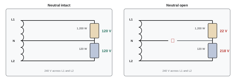
An open neutral is one of the most destructive faults in a building. When the neutral of a 120/240 V service or multiwire circuit opens, 120 V loads on the two lines are no longer connected to the center point; instead, the loads on line 1 and those on line 2 are in series across 240 V, and the voltage divides according to their impedances.
Worked problem
Voltage division after an open neutral
With an open service neutral, line 1 still supplies a 1,200 W heater (120 V rating) and line 2 a 120 W set of electronics and lighting. Treating the loads as resistances fixed at their 120 V values, what voltage appears across each?
Show solution
- Resistances: heater \(R_1 = 120^2/1{,}200 = 12\ \Omega\); electronics \(R_2 = 120^2/120 = 120\ \Omega\).
- In series across 240 V: \(I = 240/132 = 1.82\) A.
- Voltages: \(V_1 = 1.82 \times 12 = 21.8\) V; \(V_2 = 1.82 \times 120 = 218\) V.
Answer: The heavily loaded side drops to about 22 V while the lightly loaded side rises to about 218 V, nearly double its rating, destroying electronics and lamps. Symptoms of a failing neutral (lights brightening when a large load starts on the other side, or dimming on one side) should be treated as urgent.
Open neutrals on services are often caused by corroded or loose connections at the meter base, weatherhead or utility drop, or by damage to underground service conductors. On three-phase four-wire systems, an open neutral shifts the neutral point toward the most heavily loaded phase, overvoltaging the lightly loaded phases in the same way.
Why the neutral is grounded, and where
Electrical systems are grounded, meaning one conductor (usually the neutral) is intentionally connected to earth, for three reasons: to limit the voltage to ground of the system conductors during normal operation, to limit overvoltages caused by lightning, line surges or accidental contact with higher-voltage lines, and to stabilize the voltage to earth.
The neutral (grounded conductor) and the equipment grounding (bonding) conductors are connected together at one point only: the service, or the source of a separately derived system such as a transformer secondary or generator. Downstream, they must be kept separate. If the neutral were also bonded to metal enclosures and grounding conductors at subpanels or equipment, part of the normal neutral current would return over the grounding conductors, conduit and building steel. This objectionable current creates voltages on metal parts, magnetic fields that disturb sensitive equipment, and confusing readings on ground-fault protection, and if the neutral opened, all the neutral current would flow on the grounding path.
Worked problem
Current on a grounding path
A subpanel is wrongly bonded, so its neutral and enclosure are connected. The feeder neutral has a resistance of 0.04 Ω and the parallel path through the equipment grounding conductor and conduit has 0.06 Ω. The neutral current is 50 A. How much current flows on the grounding path, and what voltage appears on the subpanel enclosure relative to the service?
Show solution
- Current divides inversely with resistance: grounding path \(= 50 \times 0.04/(0.04 + 0.06) = 20\) A.
- Voltage: \(20 \times 0.06 = 1.2\) V on the enclosure relative to the service grounding point.
Answer: About 20 A of normal current flows on conduit and grounding conductors, putting 1.2 V on metal parts under normal conditions, and the full neutral current if the neutral opens. The bond belongs only at the service or source.
Kinds of system grounding
| System | Description | Ground-fault behavior | Typical use |
|---|---|---|---|
| Solidly grounded wye | neutral connected directly to ground | a ground fault draws large current and trips the overcurrent device | most commercial and residential systems: 120/240 V, 120/208 V, 347/600 V, 277/480 V |
| Ungrounded delta or wye | no intentional connection to ground | first ground fault draws only small capacitive current; nothing trips; second fault on another phase is a short circuit | older industrial plants valuing continuity |
| High-resistance grounded wye | neutral grounded through a resistor limiting fault current to a few amperes | first fault draws a few amperes, alarms but does not trip; transient overvoltages controlled | industrial and data center 480 V and 600 V systems |
| Low-resistance grounded | resistor limits fault current to a few hundred amperes | faults trip by sensitive ground relays; damage limited | medium-voltage industrial systems |
| Corner-grounded delta | one phase of a delta grounded | ground faults on the other phases trip; the grounded phase must be identified | some older industrial systems |
The high-leg (center-tapped) delta, in which one transformer of a 240 V delta bank is center-tapped to provide 120/240 V single-phase and 240 V three-phase, is still found in older US commercial buildings. The phase opposite the center tap, the high leg, is about 208 V to ground; NEC 110.15 requires it to be marked orange, and 408.3(E) requires it to be the B phase in panelboards. It must never be used for 120 V loads.
Ground faults in solidly grounded systems
When an ungrounded conductor contacts a grounded metal enclosure, current flows through the fault, back through the equipment grounding conductor to the service or source bond, and through the neutral (or the transformer winding) to complete the circuit. The current is limited only by the impedance of this loop: the transformer, the ungrounded conductor, and the return path. If the return path has low impedance, the current is large enough to trip the breaker quickly, and while the fault lasts the voltage on the enclosure is limited.
Earth itself is a poor return path. A ground rod typically has a resistance of 5 to 25 Ω or more to remote earth, so a fault relying on the earth to return current would draw only a few amperes, far too little to trip a 20 A breaker, while leaving the enclosure energized at dangerous voltage. This is why an effective ground-fault current path through bonding conductors back to the source is required, and why the ground rod is not a substitute for bonding.
Worked problem
Why earth is not a fault return path
A 120 V circuit faults to the metal frame of a pump that is grounded only by a local ground rod of 15 Ω, while the service ground electrode measures 10 Ω. What fault current flows, and what voltage appears on the pump frame? Compare with a bonding conductor path of 0.3 Ω total loop impedance.
Show solution
- Earth path: \(I = 120/(15 + 10) = 4.8\) A. Frame voltage relative to remote earth: \(4.8 \times 15 = 72\) V.
- Bonded path: \(I = 120/0.3 = 400\) A, which trips a 20 A breaker almost instantly.
Answer: Through earth only 4.8 A flows, the breaker never trips, and the frame sits at 72 V indefinitely, a lethal shock hazard. A proper bonding conductor makes the fault current large enough to clear the fault in a fraction of a second.
Ground faults in ungrounded and resistance-grounded systems
In an ungrounded system, the phases are coupled to ground only through the capacitance of cables and equipment. A first ground fault on one phase simply connects that phase to ground: little current flows (a few amperes of capacitive charging current), nothing trips, and the system keeps running, which is why ungrounded systems were favored in continuous-process industries. But the other two phases now sit at full line-to-line voltage to ground, stressing insulation, and if a second fault occurs on another phase before the first is found, the result is a phase-to-phase short circuit through the grounding system, possibly in two different pieces of equipment. Intermittent arcing ground faults can also build up transient overvoltages of several times normal through repeated charging of the system capacitance.
Ungrounded systems require ground detectors that show when a phase is faulted. The simplest uses three lamps connected from each phase to ground: normally all glow equally dimly; a ground fault on one phase darkens its lamp and brightens the other two. Modern systems use monitoring relays.
High-resistance grounding keeps the continuity advantage while avoiding the overvoltages: a resistor between the neutral and ground limits fault current to a value slightly above the system's capacitive charging current (typically 1 to 10 A), which damps arcing transients. A first fault alarms rather than trips; a pulsing feature switches part of the resistor in and out so that the pulsing current can be traced with a clamp meter to locate the fault. High-resistance grounding is widely used on 480 V and 600 V systems in industrial plants and data centers, but not for systems supplying line-to-neutral loads, because the neutral is not solidly grounded.
Worked problem
Sizing a grounding resistor
A 600 V three-phase system has a measured capacitive charging current of 2.5 A for a ground fault. A high-resistance grounding resistor is chosen to allow 5 A. What resistance is needed?
Show solution
- Line-to-neutral voltage: \(600/\sqrt3 = 346\) V.
- Resistance: \(346/5 = 69\ \Omega\).
Answer: About 69 Ω, giving a fault current of 5 A (plus the capacitive component, for a total of about 5.6 A). The resistor current exceeding the charging current ensures transient overvoltages are damped.
Common mistakes
MistakePlacing both circuits of a multiwire branch circuit on the same line.
InsteadConnect them to different lines or phases so the neutral carries the difference.
MistakeUsing device terminals to carry a shared neutral.
InsteadPigtail neutrals so removing a device cannot open the neutral.
MistakeBonding neutral and ground at subpanels.
InsteadBond only at the service or the source of a separately derived system.
MistakeRelying on a ground rod to clear faults.
InsteadProvide a low-impedance bonding path back to the source.
MistakeLeaving a first ground fault on an ungrounded or HRG system unrepaired.
InsteadLocate and repair it promptly before a second fault causes a short circuit.
Summary and key terms
- In 120/240 V systems the neutral carries the difference of the line currents; 240 V loads add no neutral current.
- Multiwire circuits save copper but need simultaneous disconnection and pigtailed neutrals.
- An open neutral puts loads in series, overvoltaging lightly loaded circuits.
- Neutral and ground are bonded only at the service or source to prevent objectionable current.
- Solidly grounded systems trip ground faults quickly through a low-impedance bonding path; earth is not an adequate return.
- Ungrounded and high-resistance grounded systems continue running after a first fault but need detection and prompt repair.
- Neutral
- The conductor connected to the center point of a system, usually grounded.
- Multiwire branch circuit
- A circuit of two or more ungrounded conductors sharing one neutral.
- Open neutral
- A break in the neutral leaving line-to-neutral loads in series.
- System grounding
- Intentional connection of a system conductor to earth.
- Objectionable current
- Normal neutral current flowing on grounding conductors and metal parts.
- Separately derived system
- A system supplied by a transformer or generator with no direct connection to the supply conductors.
- Effective ground-fault path
- A low-impedance path that carries fault current back to the source.
- Ungrounded system
- A system with no intentional connection to ground.
- High-resistance grounding
- Grounding through a resistor limiting fault current to a few amperes.
- High leg
- The phase of a center-tapped delta about 208 V above ground.
Practice problems
Work each problem on paper first, then reveal the answer to check.
Line 1 carries 40 A and line 2 carries 25 A of 120 V load. Neutral current?
Show answer
15 A.
A 240 V load of 20 A is added. Neutral current now?
Show answer
Still 15 A.
Two 120 V loads of 60 Ω and 30 Ω in series after an open neutral on 240 V. Voltage across the 60 Ω load?
Show answer
160 V.
What symptom suggests a failing service neutral?
Show answer
Lights brightening or dimming on one side when large loads switch.
Where are neutral and ground bonded?
Show answer
At the service or source of a separately derived system only.
Fault current through a 20 Ω earth path on 120 V (source electrode 5 Ω)?
Show answer
4.8 A.
Voltage to ground of the unfaulted phases on an ungrounded 480 V system with one phase grounded?
Show answer
480 V.
Resistance for a 3 A HRG on a 480 V system?
Show answer
\(277/3 = 92\ \Omega\).
Why is HRG not used where line-to-neutral loads are served?
Show answer
The neutral is not solidly grounded.
Voltage to ground of the high leg on a 240 V center-tapped delta?
Show answer
About 208 V.
Lesson quiz · 5 questions
Score 60% or more to complete this lesson.
Create a free account to save your progress, take quizzes and earn a certificate.