
ELEC-210 · Lesson 1 of 12 · 33 min
AC waveforms and phasors
Almost all the power an electrician works with is alternating current. The receptacle in a kitchen, the service entrance of a factory and the output of a wind turbine all deliver a voltage that reverses direction 120 times a second. ELEC-110 dealt with direct current, where voltage and current are steady and Ohm's law and the power formulas apply directly. With AC, voltages and currents are constantly changing, and coils and capacitors make current lead or lag the voltage, so new tools are needed: RMS values, phase angles and phasors. This course builds those tools and applies them to the equipment electricians install every day: motors, lighting, capacitor banks, three-phase services and transformers.
This lesson covers how AC is produced, how sine waves are described, what meters actually measure, phase relationships and phasor diagrams, and resistive AC circuits. Later lessons cover inductance and capacitance, resonance and harmonics, power factor, power measurement, three-phase systems, neutrals and grounding, transformers, voltage drop, fault current and troubleshooting, as set out at the end of this lesson.
Why alternating current?
AC won the "war of the currents" of the 1880s and 1890s mainly because of the transformer, which changes AC voltage up or down efficiently with no moving parts (Lesson 8). High voltage reduces current and therefore losses on long lines, and transformers bring the voltage back down to safe levels at the customer. AC is also produced naturally by rotating generators, and AC motors, especially the three-phase induction motor, are simple, rugged and cheap. DC still has important uses, such as batteries, electronics, solar panels and long-distance HVDC links, and power electronics now convert between the two freely.
Generating a sine wave
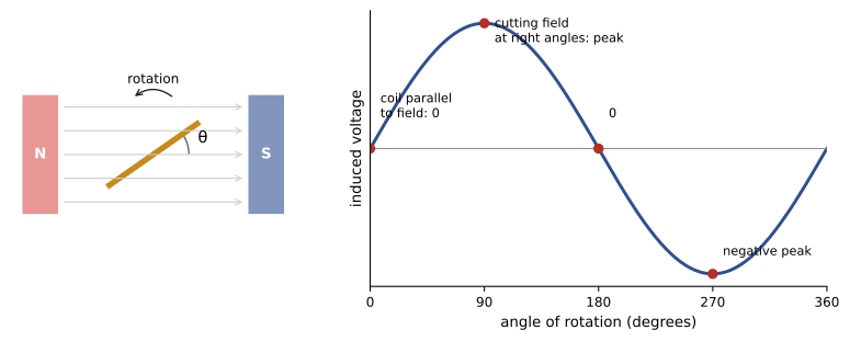
When a coil rotates at constant speed in a uniform magnetic field, the voltage induced in it varies with the sine of the angle of rotation: zero when the coil moves parallel to the field lines, maximum when it cuts across them at right angles, and reversed in polarity during the second half of each revolution. One complete revolution of a two-pole generator produces one cycle of AC:
where \(V_p\) is the peak voltage, \(f\) the frequency in hertz (cycles per second) and \(\omega = 2\pi f\) the angular frequency in radians per second. North American power systems run at 60 Hz, so one cycle takes \(T = 1/f = 1/60\) s \(= 16.7\) ms. Much of the rest of the world uses 50 Hz. A generator with more poles produces more cycles per revolution, so it turns more slowly for the same frequency: \(f = Np/120\), with \(N\) in revolutions per minute and \(p\) the number of poles. A two-pole generator turns at 3600 r/min, a four-pole machine at 1800 r/min, and a large hydro generator with 72 poles at only 100 r/min.
Describing a sine wave
Several values describe the size of an AC waveform:
- Instantaneous value: the voltage or current at a particular instant, \(v(t)\) or \(i(t)\).
- Peak value \(V_p\): the maximum, reached twice per cycle (once positive, once negative).
- Peak-to-peak value \(V_{pp} = 2V_p\): from the positive peak to the negative peak, easily read on an oscilloscope.
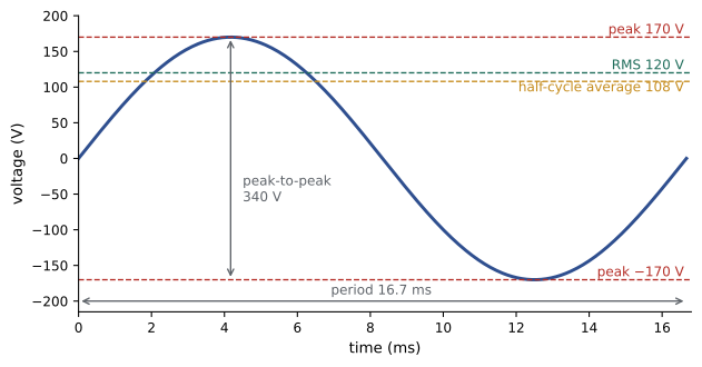
- Average value: over a full cycle the average of a sine wave is zero, so the average of one half cycle is used: \(V_{avg} = 0.637\,V_p\).
- RMS (root mean square) or effective value: \(V_{rms} = V_p/\sqrt2 = 0.707\,V_p\).
What RMS means
The RMS value of an AC voltage is the DC voltage that would produce the same heating in a resistor. Because power in a resistor is \(V^2/R\), the effective value is found by squaring the waveform, taking the mean over a cycle, and taking the square root, hence "root mean square". For a sine wave this gives \(V_p/\sqrt2\). RMS is the value that matters for heating, so it is used for all ratings: a "120 V" receptacle has an RMS voltage of 120 V, and the current rating of a breaker, conductor or motor is an RMS current. Unless stated otherwise, AC voltages and currents are always RMS.
Worked problem
Peak voltages of common systems
Find the peak voltage of a 120 V receptacle, of the 277 V line-to-neutral voltage of a 277/480 V system, and of the 480 V line-to-line voltage.
Show solution
- \(V_p = \sqrt2 \times V_{rms} = 1.414 \times V_{rms}\).
- 120 V: \(1.414 \times 120 = 170\) V.
- 277 V: \(1.414 \times 277 = 392\) V; 480 V: \(1.414 \times 480 = 679\) V.
Answer: 170 V, 392 V and 679 V. Insulation, test equipment and components must withstand the peak, not just the RMS value, which is one reason 480 V equipment is commonly rated for 600 V insulation.
| To find | From peak | From RMS | From average |
|---|---|---|---|
| Peak | — | × 1.414 | × 1.571 |
| RMS | × 0.707 | — | × 1.111 |
| Average (half cycle) | × 0.637 | × 0.900 | — |
| Peak-to-peak | × 2 | × 2.828 | × 3.142 |
Meters and true RMS
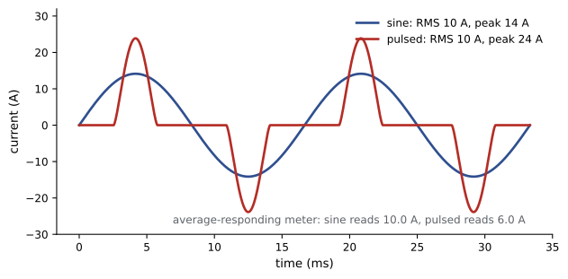
Many inexpensive meters do not actually compute RMS. They measure the average of the rectified waveform and multiply by 1.111, the ratio of RMS to average for a sine wave. These average-responding meters read correctly only for pure sine waves. Modern loads, such as variable frequency drives, LED drivers, computer power supplies and battery chargers, draw current in short pulses, producing distorted waveforms with a much higher peak relative to their RMS value. An average-responding meter can read such currents 20 to 40% low, which may lead to undersized conductors or a failure to recognize an overloaded neutral. A true-RMS meter computes the actual RMS value and should be used for any modern electrical work.
The crest factor, the ratio of peak to RMS, describes how peaky a waveform is: 1.414 for a sine wave, but often 2 to 3 for the current drawn by electronic loads. Meters specify the maximum crest factor at which their true-RMS reading remains accurate.
Worked problem
Average-responding meter on a distorted current
The current to a bank of computer power supplies has a true RMS value of 10.0 A and a crest factor of 2.5. Its half-cycle average is 6.4 A. What does an average-responding meter read? What does a true-RMS meter read?
Show solution
- Average-responding: \(1.111 \times 6.4 = 7.1\) A.
- True RMS: 10.0 A.
Answer: The average-responding meter reads 7.1 A, 29% low. Sizing conductors or judging breaker loading from that reading would be unsafe. The peak current is \(2.5 \times 10 = 25\) A.
Phase and phase angle
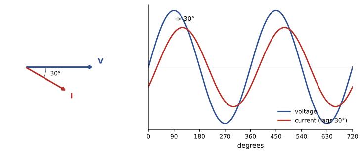
Two sine waves of the same frequency may not reach their peaks at the same time. The difference in timing, expressed as an angle, is the phase difference. One full cycle is 360°, so at 60 Hz, 1 ms corresponds to \(360° \times 60 \times 0.001 = 21.6°\). If waveform A reaches its positive peak before waveform B, A is said to lead B, and B lags A. Writing the waveforms with a phase angle:
describes a current that lags the voltage by \(\theta\). In a purely resistive circuit, current and voltage are in phase (\(\theta = 0\)). In inductive circuits such as motors, current lags; in capacitive circuits, current leads. The phase angle between voltage and current is what makes AC power calculations different from DC, as Lesson 4 shows.
Worked problem
Phase difference from an oscilloscope
On an oscilloscope, a motor's current waveform crosses zero going positive 2.0 ms after the voltage waveform does, at 60 Hz. What is the phase angle, and does the current lead or lag?
Show solution
- Period: 16.67 ms.
- Angle: \(2.0/16.67 \times 360° = 43.2°\).
Answer: The current lags the voltage by about 43°, typical of a lightly loaded induction motor.
Phasors
Drawing and adding sine waves point by point is tedious. A phasor represents a sine wave as an arrow whose length is the RMS value and whose angle is the phase angle, rotating counterclockwise at the system frequency. Because all voltages and currents in a circuit rotate together at 60 Hz, the rotation can be ignored and the phasors drawn at a fixed instant. A voltage of 120 V at 0° and a current of 10 A lagging by 30° are written \(120\angle 0°\) V and \(10\angle -30°\) A.
Phasors add like vectors: place them head to tail, or add their horizontal and vertical components. This is how voltages around a series AC circuit, or currents at a junction, are combined, since simply adding the RMS values gives the wrong answer when the phasors are not in phase.
Worked problem
Adding two voltages that are out of phase
Two sources in series produce 100 V at 0° and 100 V at 60°. What is the total voltage?
Show solution
- First: \(X_1 = 100\), \(Y_1 = 0\).
- Second: \(X_2 = 100\cos 60° = 50\), \(Y_2 = 100\sin 60° = 86.6\).
- Sum: \(X = 150\), \(Y = 86.6\); \(V = \sqrt{150^2 + 86.6^2} = 173.2\) V at \(\tan^{-1}(86.6/150) = 30°\).
Answer: 173 V at 30°, not 200 V. Two equal voltages 60° apart add to \(\sqrt3\) times either one; the same geometry explains why the line-to-line voltage of a three-phase system is \(\sqrt3\) times the line-to-neutral voltage (Lesson 6).
Resistive AC circuits
In a circuit containing only resistance, such as an electric heater, an incandescent lamp or a resistance-type water heater element, current is in phase with voltage and Ohm's law applies directly to RMS values: \(I = V/R\) and \(P = VI = I^2R = V^2/R\), with \(V\) and \(I\) as RMS values. Series and parallel resistive circuits are solved exactly as in ELEC-110. The instantaneous power \(p = vi\) pulses between zero and twice the average at twice the line frequency (120 times a second), but it is never negative: a resistor always takes energy from the source.
Worked problem
An AC heater
A baseboard heater is rated 2000 W at 240 V. Find its current, resistance and peak current. What power does it produce if connected to 208 V by mistake?
Show solution
- Current: \(2000/240 = 8.33\) A RMS; peak \(1.414 \times 8.33 = 11.8\) A.
- Resistance: \(240/8.33 = 28.8\) Ω.
- At 208 V: \(208^2/28.8 = 1502\) W.
Answer: 8.33 A, 28.8 Ω and 11.8 A peak. On 208 V it produces only 1500 W, 25% less, because power varies with the square of voltage. This is a common mistake in buildings with 120/208 V services, where heaters rated for 240 V underperform.
Harmonics: a first look
Distorted waveforms like the power supply current above can be broken down into a sum of sine waves: the fundamental at 60 Hz and harmonics at whole-number multiples, 180 Hz (3rd), 300 Hz (5th), 420 Hz (7th) and so on. Harmonic currents add to the RMS current and heating without contributing useful power, overheat transformers and neutral conductors, and can distort the voltage for other equipment. Total harmonic distortion (THD) expresses the harmonic content as a percentage of the fundamental. Lessons 3 and 6 return to harmonics and their effect on three-phase neutrals, where the 3rd harmonic causes particular problems.
How this course is organized
The twelve lessons build from single-phase AC theory to three-phase systems, transformers and practical system calculations:
- Lesson 1 (this lesson): AC waveforms, RMS values, true-RMS meters and phasors.
- Lesson 2: inductance, capacitance, reactance and impedance in series and parallel circuits.
- Lesson 3: resonance, harmonics and filters.
- Lesson 4: real, reactive and apparent power, power factor and its correction.
- Lesson 5: power measurement, energy and demand metering, and power quality.
- Lesson 6: three-phase systems, power, unbalance and phase sequence.
- Lesson 7: neutrals, multiwire circuits, system grounding and ground faults.
- Lesson 8: transformers: ratings, losses, impedance, taps, polarity and protection.
- Lesson 9: three-phase transformer connections, banks, paralleling and testing.
- Lesson 10: voltage drop in AC circuits.
- Lesson 11: fault current and equipment ratings.
- Lesson 12: troubleshooting AC systems and a capstone project.
Common mistakes
MistakeTreating "120 V" as the peak voltage.
InsteadAC ratings are RMS; the peak of a 120 V supply is 170 V.
MistakeMeasuring electronic load currents with an average-responding meter.
InsteadUse a true-RMS meter; average-responding meters can read distorted currents 20 to 40% low.
MistakeAdding AC voltages or currents arithmetically when they are out of phase.
InsteadAdd them as phasors, by components.
MistakeApplying sine-wave conversion factors to distorted waveforms.
InsteadThe 0.707 and 1.111 factors are valid only for pure sine waves.
MistakeConnecting a 240 V heater to 208 V and expecting rated output.
InsteadPower falls with the square of voltage: about 75% of rating.
Summary and key terms
- AC dominates because transformers change voltage easily; generators naturally produce sine waves.
- v = V_p sin(2πft); North America uses 60 Hz, period 16.7 ms; f = Np/120.
- Peak, peak-to-peak (2V_p), half-cycle average (0.637V_p) and RMS (0.707V_p) describe a sine wave.
- RMS is the heating-equivalent value; all AC ratings are RMS.
- Average-responding meters err on distorted waveforms; use true-RMS meters. Crest factor = peak/RMS.
- Phase angle describes timing differences; current lags in inductive and leads in capacitive circuits.
- Phasors represent sine waves as arrows; they add by components.
- In resistive circuits, V and I are in phase and DC formulas apply to RMS values.
- Distorted waveforms contain harmonics at multiples of 60 Hz.
- Alternating current
- Current that periodically reverses direction.
- Cycle
- One complete repetition of a waveform.
- Frequency
- The number of cycles per second, in hertz.
- Period
- The time for one cycle, T = 1/f.
- Peak value
- The maximum instantaneous value of a waveform.
- Peak-to-peak value
- The difference between positive and negative peaks.
- RMS value
- The effective value producing the same heating as an equal DC value.
- True-RMS meter
- A meter that computes the actual RMS value of any waveform.
- Crest factor
- The ratio of peak value to RMS value.
- Phase angle
- The angular difference in timing between two waveforms of the same frequency.
- Lead and lag
- Whether a waveform reaches its peak before or after another.
- Phasor
- A rotating arrow representing the magnitude and phase of a sine wave.
- Harmonic
- A sine wave at a whole-number multiple of the fundamental frequency.
- Total harmonic distortion
- Harmonic content as a percentage of the fundamental.
Practice problems
Work each problem on paper first, then reveal the answer to check.
What is the period of a 50 Hz waveform?
Show answer
20 ms.
A generator has 6 poles and runs at 1200 r/min. What frequency does it produce?
Show answer
1200 × 6/120 = 60 Hz.
A 208 V supply has what peak voltage?
Show answer
294 V.
A sine wave has a peak of 50 V. What are its RMS and half-cycle average values?
Show answer
35.4 V and 31.9 V.
An oscilloscope shows 340 V peak-to-peak. What is the RMS voltage?
Show answer
170 V peak; 120 V RMS.
Why should a true-RMS meter be used on a circuit feeding LED drivers?
Show answer
Their current is distorted; average-responding meters read it low.
At 60 Hz, what time difference corresponds to 90°?
Show answer
16.67/4 = 4.17 ms.
Add 50 V at 0° and 50 V at 90°.
Show answer
70.7 V at 45°.
A 1500 W, 120 V heater: find current and resistance.
Show answer
12.5 A; 9.6 Ω.
What is the 5th harmonic frequency on a 60 Hz system?
Show answer
300 Hz.
Lesson quiz · 5 questions
Score 60% or more to complete this lesson.
Create a free account to save your progress, take quizzes and earn a certificate.