
ELEC-210 · Lesson 12 of 12 · 31 min
Troubleshooting AC systems and a capstone project
The theory of this course becomes most valuable when something goes wrong: a breaker that trips for no obvious reason, a transformer that runs hot, a motor that burns out, capacitors that fail, lights that flicker. Good troubleshooters combine a systematic method, the right instruments used safely, and an understanding of how AC systems behave, so that each measurement narrows the possibilities. This lesson presents a troubleshooting method for AC systems, works through common problems and their signatures, and finishes with a capstone project in which you apply the course to the electrical design checks for a small commercial building.
A method for AC troubleshooting
The method from ELEC-110 applies, with additions for AC systems:
- Gather information: what exactly happens, when it started, what changed recently (new equipment, a utility change, added load, renovations), whether it is constant, intermittent or tied to particular times or loads.
- Review the system: single-line diagrams, panel schedules, nameplates and settings of the equipment involved.
- Plan measurements that distinguish between likely causes, and decide which can be made safely de-energized and which require energized work.
- Measure: voltage (line to line, line to neutral, neutral to ground), current in each phase and the neutral, power and power factor, harmonics, temperature by infrared scan, insulation resistance with the equipment isolated.
- Interpret, repair the cause rather than the symptom, and verify the fix under the conditions that produced the problem.
- Record what was found and done, so the next person benefits.
Safety is part of the method, not an afterthought. Energized measurements require justification, authorization, appropriate PPE and instruments rated for the measurement category (Lesson 5); work on conductors requires lockout, tagout and verification of absence of voltage, following CSA Z462 in Canada or NFPA 70E in the US. Remember the special hazards of AC equipment: capacitors that hold charge after disconnection (Lesson 2), current transformer secondaries that must not be opened under load, and backfeed from generators, UPSs, solar inverters or multiwire circuits.
Common problems and their signatures
Breakers that trip
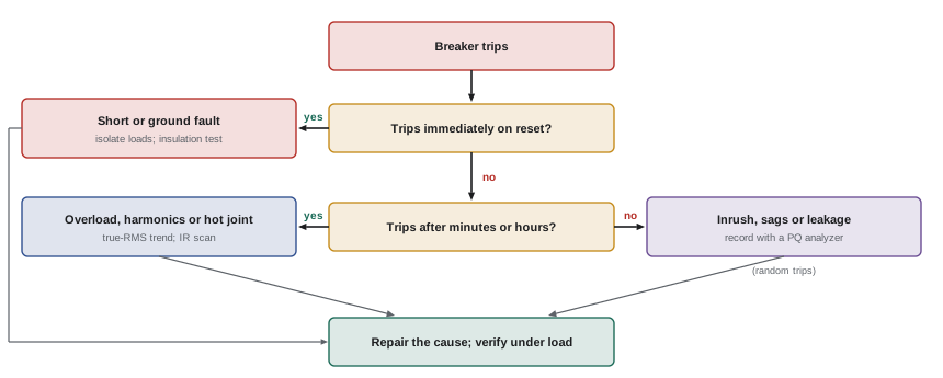
The timing tells a lot. Immediate tripping on reset indicates a short circuit or ground fault still present: isolate loads, then test the circuit's insulation resistance. Tripping after minutes or hours suggests overload or heating: measure true RMS current over time; check for harmonic currents that an averaging meter would miss (Lesson 3), and for loose connections heating the breaker (an infrared scan shows them). Random trips that cannot be tied to load suggest inrush from motors, transformers or LED drivers (many small drivers on one circuit can draw large combined inrush), leakage currents on GFCI or ground-fault protection, or voltage disturbances (Lesson 5).
Worked problem
Tripping lighting circuit
A 20 A, 120 V circuit supplying 40 LED fixtures (each 30 W at 0.95 power factor) trips occasionally when switched on, never while running. The running current measures 10.5 A. What is the likely cause and fix?
Show solution
- Running current is well within rating, so overload is not the cause.
- Tripping only at switch-on points to inrush: each driver's input capacitor charges at turn-on, and 40 drivers together can draw hundreds of amperes for a fraction of a millisecond, enough to trip the magnetic (instantaneous) element.
Answer: Inrush current from the LED drivers. Remedies include dividing the fixtures over two circuits, using inrush current limiters or switching relays rated for capacitive loads, selecting drivers with lower inrush, or a breaker with a higher instantaneous trip characteristic where permitted. Driver data sheets list inrush current and the maximum number per breaker.
Overheating neutrals and transformers
A neutral carrying more than any phase on a 120/208 V system, with phase currents balanced, is the signature of triplen harmonics from electronic loads (Lesson 3). Measure the neutral current and its harmonic content; solutions include larger neutrals, K-rated or derated transformers and harmonic mitigation. A transformer running hot with moderate load may be overloaded by harmonics, have blocked ventilation, be on the wrong tap (overexcited), or have an internal fault indicated by unequal winding resistances or turns ratios (Lesson 9).
Voltage problems
Low voltage at the end of a feeder that rises when load drops points to voltage drop (Lesson 10) or an undersized transformer; low voltage at all loads at all times suggests the transformer tap or the supply. Voltages that swing in opposite directions on two lines of a 120/240 V system when loads change are the classic signature of a failing neutral (Lesson 7), urgent because the next stage may destroy equipment. Unbalanced three-phase voltages come from unbalanced single-phase loading, an open-delta bank or a high-resistance connection in one phase.
Worked problem
Voltage unbalance and a motor
A three-phase motor runs hot. The line voltages measure 470, 480 and 455 V. Calculate the voltage unbalance. What effect does it have?
Show solution
- Average: \((470 + 480 + 455)/3 = 468.3\) V.
- Maximum deviation: \(468.3 - 455 = 13.3\) V. Unbalance \(= 13.3/468.3 = 2.8\%\).
- A common rule of thumb is that temperature rise in the most heated winding increases by about twice the square of the percentage unbalance: \(2 \times 2.8^2 \approx 16\%\).
Answer: About 2.8% unbalance, raising winding temperature rise by roughly 16% and shortening insulation life. Motor standards recommend derating above 1% unbalance. Find and correct the cause, such as a poor connection on the low phase or uneven single-phase loading, rather than oversizing the motor.
Single-phasing
When one phase of a three-phase supply to a motor is lost (a blown fuse, broken conductor or failed contact), a running motor continues to turn on two phases, drawing about 1.7 times its normal current on the remaining lines, and overheats quickly; a stopped motor will not start and hums. Overload relays should trip, but only if they are correctly set and sensitive to the condition; phase-loss relays provide better protection. After a single-phasing failure, find why the phase was lost before replacing the motor.
Capacitor failures
Power factor capacitors that bulge, leak or blow fuses repeatedly are often victims of harmonic resonance (Lesson 3) or overvoltage. Measure harmonic currents in the capacitor bank and the voltage distortion at the bus; if a resonance is near a harmonic present, replace the bank with a detuned design.
Intermittent faults and hot connections
Loose or corroded connections are among the most common causes of failures and fires. Their resistance generates heat that worsens the connection further. Infrared thermography under load (at least 40% of rated load for meaningful results) finds them: a connection 10 °C hotter than similar connections under the same load warrants investigation, and 40 °C or more calls for prompt repair. Voltage drop across a closed connection or contact, measured under load, also reveals high resistance.
Insulation resistance testing
A megohmmeter applies a DC test voltage (typically 500 V for 120/240 V circuits, 1,000 V for 600 V class equipment) and measures the leakage current to calculate insulation resistance. Before testing, the circuit must be de-energized, locked out and isolated from equipment that could be damaged (electronic devices, surge protectors, drives). Readings of hundreds of megohms are typical for good wiring; readings below about 1 MΩ indicate a problem. Trends over time are more informative than single readings, and readings should be corrected to a standard temperature, because insulation resistance falls roughly by half for every 10 °C rise.
Worked problem
Temperature correction
A motor winding measures 40 MΩ at 40 °C. Its acceptance record shows 120 MΩ at 20 °C. Using the halving-per-10 °C rule, has the insulation deteriorated?
Show solution
- Correct to 20 °C: 20 °C cooler is two 10 °C steps, so multiply by \(2^2 = 4\): \(40 \times 4 = 160\) MΩ.
Answer: The corrected value, 160 MΩ, is comparable to the acceptance reading, so no deterioration is indicated. Comparing the raw 40 MΩ with 120 MΩ would have suggested a false problem.
Capstone project: electrical checks for a small commercial building
A two-story office and light-assembly building is supplied at 277/480 V from a utility pad-mounted transformer. A 150 kVA, 480 V delta to 120/208 V wye dry-type transformer supplies receptacles, computers and LED lighting; 480 V loads include rooftop HVAC units and a 30 hp air compressor. Your task is to check the design using the methods of this course.
Step 1: Loads and the transformer
The 120/208 V demand load is 105 kVA, of which about 60% is electronic (computers, LED drivers, chargers) with current THD near 80%. The transformer is loaded to 70% of nameplate, but harmonic heating means a standard transformer would run hotter than this suggests. Specify a K-13 rated transformer, or derate a standard unit, and plan 20% to 25% spare capacity for growth (Lessons 3 and 9).
Step 2: Neutral sizing
With a large share of single-phase electronic loads, triplen harmonics will make the neutral current approach or exceed phase current. Specify a full-size (preferably oversized) neutral on the secondary feeder and panel, count the neutral as current-carrying for derating, and avoid shared neutrals on circuits feeding computers (Lessons 3 and 7).
Step 3: Power factor
The utility bill shows a power factor of 0.86 and a penalty below 0.90. Correction of about 15% of the demand kVA is required. Because of the harmonic loads, specify a detuned capacitor bank with 7% reactors, and check its resonance with the utility transformer (Lessons 3 and 4).
Step 4: Voltage drop
The farthest 120 V receptacle circuit runs 40 m (130 ft) from its panel; the compressor feeder is 70 m (230 ft) long. Check both for 3% voltage drop and the overall 5%, using effective impedance for the feeder and the motor starting drop for the compressor (Lesson 10). Upsize conductors (and bonding conductors proportionally) where necessary.
Step 5: Fault current
Obtain the utility's available fault current at the service, calculate it at the main switchboard, at the 150 kVA transformer secondary (about 14 kA at 208 V with 3% impedance and an infinite source on its primary, since its full-load current is 416 A), and at each panel, adding motor contribution at the 600 V or 480 V switchboard. Confirm that every breaker and panel has adequate interrupting rating and SCCR, and that the HVAC units and compressor controller have SCCRs above the available fault current at their locations. Mark service equipment as required (Lesson 11).
Step 6: Grounding and measurement
Confirm that the 120/208 V system is bonded at the transformer or its first disconnect as a separately derived system, and nowhere else (Lesson 7). Plan a power quality survey after occupancy to verify harmonic levels, power factor and demand, and to establish baselines for future troubleshooting (Lesson 5).
Worked problem
Capstone check: transformer secondary fault current
For the 150 kVA, 3% impedance transformer at 208 V, calculate the full-load current and the secondary fault current assuming an infinite primary source. If the panel 25 m away is fed by conductors whose impedance per phase is 0.012 Ω, estimate the fault current at the panel (treat the transformer impedance as purely reactive for simplicity and add magnitudes).
Show solution
- FLA: \(150{,}000/(\sqrt3 \times 208) = 416\) A. Fault current: \(416/0.03 = 13{,}900\) A.
- Transformer impedance: \(208/(\sqrt3 \times 13{,}900) = 0.00864\ \Omega\).
- Adding magnitudes: \(0.00864 + 0.012 = 0.0206\ \Omega\); fault current \(\approx 208/(\sqrt3 \times 0.0206) = 5{,}800\) A.
Answer: About 13.9 kA at the transformer and about 5.8 kA at the panel (adding magnitudes is conservative toward lower current here; a full calculation with resistance and reactance separated gives a somewhat higher value). Panels at the transformer need ratings above 14 kA; the remote panel could use 10 kA equipment, confirmed by a full calculation.
The capstone shows how the topics of this course connect: harmonics affect transformers, neutrals and capacitors; power factor correction interacts with resonance; voltage drop and fault current both depend on conductor impedance and transformer impedance; and grounding determines how faults are cleared. An electrician who understands these connections can install systems that work, and find out why they do not.
Common mistakes
MistakeReplacing a tripping breaker with a larger one.
InsteadFind the cause: overload, short, ground fault, harmonics, inrush or a hot connection.
MistakeMeasuring distorted currents with an averaging meter.
InsteadUse true-RMS instruments and check the neutral.
MistakeIgnoring small voltage unbalance.
InsteadA few percent unbalance raises motor heating sharply; correct the cause.
MistakeComparing insulation readings taken at different temperatures.
InsteadCorrect readings to a standard temperature before comparing.
MistakeChecking design topics separately.
InsteadConsider interactions: harmonics, capacitors, impedance, fault current and grounding.
Summary and key terms
- AC troubleshooting gathers information, reviews the system, plans safe measurements, interprets and verifies.
- Timing and signatures distinguish shorts, overloads, harmonics, inrush and disturbances behind breaker trips.
- Hot neutrals indicate triplen harmonics; swinging line voltages indicate a failing neutral; unbalance and single-phasing overheat motors.
- Capacitor failures often point to harmonic resonance; infrared scans and connection voltage drops find hot connections.
- Insulation resistance tests need isolation, appropriate test voltages and temperature correction.
- The capstone combines transformer, neutral, power factor, voltage drop, fault current and grounding checks.
- Inrush current
- The high current drawn briefly when equipment is energized.
- Voltage unbalance
- Maximum deviation from average line voltage divided by the average.
- Single-phasing
- Loss of one phase of a three-phase supply to a motor.
- Phase-loss relay
- A relay that detects the loss or reversal of a phase.
- Infrared thermography
- Imaging temperatures to find hot connections and overloaded equipment.
- Megohmmeter
- An instrument measuring insulation resistance at a high DC voltage.
- Temperature correction
- Adjusting insulation readings to a standard temperature.
- Backfeed
- Energization of a circuit from an unexpected source.
- Baseline measurement
- Recorded normal values used for comparison in later troubleshooting.
- Root cause
- The underlying reason for a failure, rather than its symptom.
Practice problems
Work each problem on paper first, then reveal the answer to check.
A breaker trips immediately on reset. Most likely cause?
Show answer
A short circuit or ground fault still present.
Phase currents balanced at 80 A, neutral 110 A on a 120/208 V panel. Cause?
Show answer
Triplen harmonics from electronic loads.
Voltage unbalance for 208, 204 and 200 V?
Show answer
Average 204, max deviation 4 V: 2.0%.
Approximate added temperature rise from 2% unbalance?
Show answer
\(2 \times 2^2 = 8\%\).
Current in the remaining lines of a single-phased running motor?
Show answer
About 1.7 times normal.
A connection 45 °C hotter than similar ones under the same load. Action?
Show answer
Prompt repair.
Insulation 30 MΩ at 30 °C corrected to 20 °C?
Show answer
60 MΩ.
Test voltage for 600 V class equipment insulation tests?
Show answer
Typically 1,000 V DC.
FLA and fault current of a 75 kVA, 208 V, 4% transformer (infinite source)?
Show answer
208 A; 5,200 A.
Why specify a detuned capacitor bank in the capstone building?
Show answer
Harmonic loads could excite resonance with a plain bank.
Lesson quiz · 5 questions
Score 60% or more to complete this lesson.
Create a free account to save your progress, take quizzes and earn a certificate.