
ELEC-210 · Lesson 3 of 12 · 30 min
Resonance, harmonics and filters
Lesson 2 showed that inductive reactance rises with frequency while capacitive reactance falls. When the two are equal, a circuit is resonant, and currents or voltages can become far larger than the supply alone would suggest. On a pure 60 Hz system this would be a curiosity, but modern electrical systems are full of currents at other frequencies: the harmonics drawn by LED drivers, computer power supplies, variable frequency drives and battery chargers. Harmonics overheat neutrals and transformers, trip breakers, distort voltage, and can excite resonance with power factor capacitors, sometimes destroying them. This lesson explains series and parallel resonance, where harmonics come from and how they are measured, their effects on wiring and equipment, and the filters and other measures electricians use to control them.
Series resonance
In a series RLC circuit, the total reactance is \(X_L - X_C\). At one frequency, the resonant frequency, the two reactances are equal and cancel:
At resonance the impedance falls to the resistance alone, so the current is limited only by \(R\), and it is in phase with the voltage. The voltages across the inductor and the capacitor individually can be much larger than the supply voltage, because each equals the current times a reactance that may be many times \(R\); they are equal and opposite, so they cancel in the total. The ratio of the reactance to the resistance at resonance is the quality factor \(Q = X_L/R\), and the voltage across each element is \(Q\) times the supply voltage.
Worked problem
Series resonance
A series circuit has \(R = 5\ \Omega\), \(L = 20\) mH and \(C = 50\ \mu\)F, supplied at 120 V of variable frequency. Find the resonant frequency, the current at resonance and the voltage across the capacitor.
Show solution
- \(f_r = 1/(2\pi\sqrt{0.020 \times 50 \times 10^{-6}}) = 1/(2\pi \times 0.001) = 159\) Hz.
- Current: \(I = 120/5 = 24\) A.
- \(X_C = X_L = 2\pi \times 159 \times 0.020 = 20\ \Omega\); \(V_C = 24 \times 20 = 480\) V.
Answer: 159 Hz, 24 A and 480 V across the capacitor, four times the supply voltage (\(Q = 4\)). A capacitor rated for 120 V would fail. This is why resonance must be considered whenever capacitors and inductances share a circuit.
Parallel resonance
In a parallel LC circuit, the inductive and capacitive branch currents are 180° apart. At the resonant frequency (the same formula for ideal components) they are equal and cancel in the supply line, so the line current is very small and the impedance seen by the source is very high. Meanwhile a large current circulates between the inductor and the capacitor. Parallel resonance is the more common problem in power systems, because power factor capacitors are connected in parallel with the inductance of the supply transformer and utility system.
The resonant frequency of a capacitor bank with the system inductance can be estimated from the short-circuit capacity at the bus and the capacitor rating. Expressed as a harmonic number (the resonant frequency divided by 60 Hz):
where \(S_{sc}\) is the short-circuit capacity in kVA at the capacitor's location and \(Q_c\) the capacitor rating in kvar.
Worked problem
Capacitor bank resonance
A 1,500 kVA transformer with 5.75% impedance supplies a 480 V switchboard. A 300 kvar capacitor bank is connected at the switchboard. Neglecting the utility impedance, at what harmonic does the bank resonate with the transformer?
Show solution
- Short-circuit capacity: \(1{,}500/0.0575 = 26{,}087\) kVA.
- \(h_r = \sqrt{26{,}087/300} = \sqrt{87} = 9.3\).
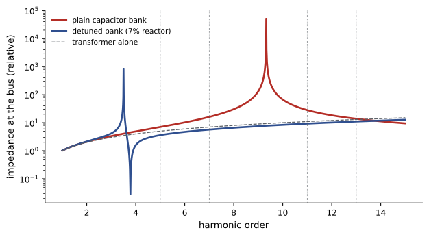
Answer: Near the 9th harmonic (about 560 Hz). If the loads produce significant 7th or 11th harmonic currents, they are close enough to be amplified; if the bank were enlarged to 500 kvar, the resonance would move to the 7.2th harmonic, close to the 7th, a dangerous combination. Utility impedance lowers the resonant frequency further.
What harmonics are
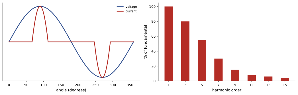
A harmonic is a sinusoidal component at an integer multiple of the fundamental frequency: the 3rd harmonic of 60 Hz is 180 Hz, the 5th is 300 Hz, the 7th 420 Hz. Any repeating waveform, however distorted, can be built from the fundamental plus harmonics (Fourier's theorem). Lesson 1 introduced the idea; here we look at the sources and effects in detail.
Harmonic currents are produced by nonlinear loads, whose current is not proportional to the voltage. The most common is the rectifier with a capacitor at the input of electronic power supplies: it draws current only in short pulses near the peaks of the voltage wave. Typical sources:
| Source | Dominant harmonics | Typical current THD |
|---|---|---|
| Single-phase electronic loads (computers, LED drivers, TVs, chargers) | 3rd, 5th, 7th, 9th | 70% to 130% without correction |
| Six-pulse drives and rectifiers (VFDs, UPSs, DC drives) | 5th, 7th, 11th, 13th | 30% to 80% without reactors |
| Twelve-pulse rectifiers | 11th, 13th | 10% to 15% |
| Arc furnaces, welders | broad spectrum, interharmonics | varies widely |
| Transformers when overexcited | 3rd, 5th | small, rising sharply above rated voltage |
| Active front-end drives, power-factor-corrected supplies | high-frequency, low magnitude | under 5% to 10% |
The amount of distortion is measured by total harmonic distortion (THD), the RMS of all harmonic components divided by the fundamental:
Current THD can be large for individual loads; voltage THD, which affects every load on the bus, is usually much smaller and should normally stay below about 5% at the service. The total RMS current includes the harmonics: \(I_{\text{RMS}} = I_1\sqrt{1 + \mathrm{THD}^2}\), which is why true-RMS meters (Lesson 1) are essential: averaging meters can read 30% to 40% low on distorted currents.
Effects of harmonics
Neutral currents in three-phase systems
In a balanced three-phase four-wire system with linear loads, the phase currents cancel in the neutral (Lesson 6). Triplen harmonics (the 3rd, 9th, 15th and other odd multiples of 3) behave differently: their waves in the three phases are in phase with each other, so instead of canceling they add in the neutral. A neutral serving many single-phase electronic loads can carry more current than any phase conductor.
Worked problem
Neutral current from third harmonics
A 120/208 V panel feeds balanced office loads. Each phase carries 100 A RMS, consisting of a 60 Hz fundamental of 80 A and a 3rd harmonic of 60 A (other harmonics neglected). What current flows in the neutral?
Show solution
- Check: \(\sqrt{80^2 + 60^2} = 100\) A per phase.
- Fundamentals cancel in the neutral; the 3rd harmonics add: \(3 \times 60 = 180\) A at 180 Hz.
Answer: 180 A in the neutral, 1.8 times the phase current. A neutral sized equal to the phase conductors would overheat. This is why feeders to electronic loads use full-size or oversized (even double) neutrals, and why codes require the neutral to be counted as a current-carrying conductor for ampacity derating when the load is mainly nonlinear.
Code requirements reflect this: NEC 220.61(C) does not permit the neutral demand reduction for the portion of load consisting of nonlinear loads supplied from a 4-wire wye system, and 310.15(E)(3) requires the neutral to be counted as a current-carrying conductor when the major portion of the load is nonlinear.
Transformers
Harmonic currents increase eddy-current losses in transformer windings roughly with the square of the harmonic order, so a transformer serving nonlinear loads runs hotter than its load in kVA suggests. Options are derating the transformer, or using a K-rated transformer designed for harmonic heating (K-4, K-13 and K-20 ratings are common, with higher numbers for more severe harmonic content). In delta-wye transformers, triplen currents from the secondary circulate in the primary delta and do not reach the supply, but they still heat the transformer.
Other effects
- Voltage distortion: harmonic currents flowing through the source impedance distort the voltage, affecting sensitive equipment, causing flat-topped voltage waves and reducing the ride-through of power supplies.
- Capacitors: capacitive reactance falls with frequency, so capacitors absorb harmonic currents, overheating and failing; at resonance the effect is amplified.
- Breakers and fuses: thermal-magnetic breakers respond to true RMS heating, but some electronic trip units sampling peaks may trip unexpectedly; fuses may run warm.
- Motors: 5th harmonic voltage produces a negative-sequence rotating field that opposes rotation, adding heat and torque pulsations.
- Neutral-to-ground voltage at receptacles caused by triplen neutral currents, which can disturb sensitive electronics.
Controlling harmonics
Harmonic problems are solved at the source, in the distribution system, or at the point of common coupling with the utility:
- Line reactors (typically 3% or 5% impedance) and DC-link chokes on drives smooth the current pulses, cutting current THD from 80% to roughly 35% to 45%.
- Multi-pulse rectifiers (12- or 18-pulse) and phase-shifting transformers cancel the 5th and 7th harmonics between groups of drives.
- Active front-end drives and power-factor-corrected supplies draw nearly sinusoidal current.
- Passive tuned filters: a capacitor in series with a reactor tuned just below a harmonic (for example 4.7th for the 5th) provides a low-impedance path that absorbs that harmonic, while also supplying power factor correction at 60 Hz.
- Detuned capacitor banks: reactors in series with power factor capacitors tuned well below the lowest significant harmonic (typically 4.2nd or about 250 Hz, often specified as 7% reactors) prevent resonance without trying to absorb harmonics.
- Active harmonic filters: power electronic devices that measure the load's harmonic currents and inject equal and opposite currents, adapting to changing loads.
- Oversized neutrals, K-rated transformers and separate circuits for sensitive equipment manage the effects that remain.
Worked problem
Detuning reactor
A 100 kvar, 480 V capacitor bank is to be detuned to 4.2 times 60 Hz (252 Hz). What reactor impedance, as a percentage of the capacitor reactance at 60 Hz, is needed?
Show solution
- Series resonance occurs where \(X_L(h) = X_C(h)\), that is, \(hX_{L1} = X_{C1}/h\), so \(X_{L1}/X_{C1} = 1/h^2\).
- \(1/4.2^2 = 0.0567\), about 5.7%.
Answer: A reactor of about 5.7% of the capacitor's 60 Hz reactance (commercial banks use 5.67% or 7% reactors, the latter tuning to about 3.8). The reactor also raises the voltage across the capacitors by about \(1/(1 - 0.057) = 1.06\), so capacitors rated above system voltage are used.
Standards and measurement
IEEE 519 sets recommended limits for harmonic voltage distortion and for current distortion at the point of common coupling with the utility, scaled by the ratio of available short-circuit current to load current: larger customers on weak systems face tighter limits. Utilities may require harmonic studies before connecting large drive or rectifier loads. Measuring harmonics needs a power quality analyzer or harmonic-capable meter that reports THD and individual harmonic magnitudes on each phase and the neutral (Lesson 5). Measurements should be taken under typical and maximum load, since harmonic content varies with loading.
Common mistakes
MistakeAdding capacitors to a system with drives without checking resonance.
InsteadEstimate \(h_r = \sqrt{S_{sc}/Q_c}\) and use detuned banks or filters where needed.
MistakeUsing a reduced neutral on feeders to electronic loads.
InsteadUse full-size or oversized neutrals; triplen harmonics add in the neutral.
MistakeMeasuring distorted currents with an averaging meter.
InsteadUse a true-RMS meter or power quality analyzer.
MistakeLoading a standard transformer to nameplate with heavy nonlinear loads.
InsteadDerate it or use a K-rated transformer.
MistakeRating capacitors at system voltage when used with reactors.
InsteadAccount for the voltage rise caused by the series reactor.
Summary and key terms
- Series resonance minimizes impedance and can produce element voltages many times the supply; parallel resonance maximizes impedance and circulating current.
- Capacitor banks resonate with system inductance at \(h_r = \sqrt{S_{sc}/Q_c}\).
- Nonlinear loads draw harmonic currents measured by THD; true-RMS measurement is essential.
- Triplen harmonics add in three-phase neutrals; harmonics heat transformers, capacitors and motors.
- Line reactors, multi-pulse and active front-end drives, tuned and detuned capacitor banks and active filters control harmonics.
- IEEE 519 sets limits at the point of common coupling; power quality analyzers measure harmonic content.
- Resonant frequency
- The frequency at which inductive and capacitive reactance are equal.
- Quality factor
- The ratio of reactance to resistance at resonance.
- Harmonic
- A component at an integer multiple of the fundamental frequency.
- Nonlinear load
- A load whose current is not proportional to the applied voltage.
- THD
- Total harmonic distortion: harmonic RMS divided by the fundamental.
- Triplen harmonics
- Odd multiples of the 3rd harmonic, which add in the neutral.
- K-rated transformer
- A transformer designed to withstand harmonic heating.
- Tuned filter
- A reactor and capacitor tuned to absorb a specific harmonic.
- Detuned capacitor bank
- A capacitor bank with series reactors that move resonance below the harmonics present.
- Active harmonic filter
- A power electronic device injecting currents that cancel load harmonics.
Practice problems
Work each problem on paper first, then reveal the answer to check.
Resonant frequency of \(L = 10\) mH and \(C = 100\ \mu\)F?
Show answer
159 Hz.
At series resonance with \(R = 10\ \Omega\) and \(X_L = 50\ \Omega\) on 120 V, the capacitor voltage?
Show answer
600 V (\(Q = 5\)).
Harmonic number of resonance for \(S_{sc} = 20{,}000\) kVA and 200 kvar?
Show answer
10.
Frequency of the 5th harmonic on a 60 Hz system?
Show answer
300 Hz.
RMS current with a 50 A fundamental and 40% THD?
Show answer
\(50\sqrt{1.16} = 53.9\) A.
Each phase carries a 3rd harmonic of 30 A. Neutral current from it?
Show answer
90 A.
Name three triplen harmonics.
Show answer
3rd, 9th, 15th.
Why do harmonics overheat transformers?
Show answer
Eddy losses rise with the square of harmonic order.
Reactor percentage to detune to the 4.5th harmonic?
Show answer
\(1/4.5^2 = 4.9\%\).
Which standard sets harmonic limits at the point of common coupling?
Show answer
IEEE 519.
Lesson quiz · 5 questions
Score 60% or more to complete this lesson.
Create a free account to save your progress, take quizzes and earn a certificate.