
ELE-370 · Lesson 7 of 12 · 38 min
Induction motors
The three-phase induction motor is the workhorse of industry. It drives pumps, fans, compressors, conveyors and machine tools; it moves the water and air in buildings and the coolant in data centers; and it accounts for most of the electricity used by motors, which in turn use more than 40% of all electricity. Its success comes from its simplicity: a squirrel-cage rotor has no brushes, no slip rings and no windings to insulate, just bars shorted by end rings, so it is cheap, rugged and nearly maintenance-free. Combined with variable-frequency drives, it now also handles most applications that once needed DC motors. This lesson explains the rotating magnetic field, slip and the equivalent circuit, the torque-speed curve and its design classes, starting methods, speed control with drives, efficiency standards and protection.
The rotating magnetic field
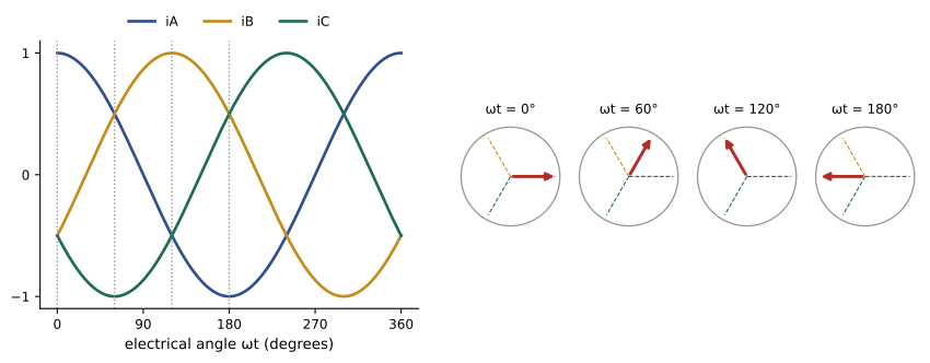
The stator of a three-phase motor carries three windings displaced 120 electrical degrees around the air gap, fed by three currents displaced 120° in time. Each winding alone produces a pulsating field along its own axis; together, they produce a field of constant magnitude that rotates around the air gap at synchronous speed:
where \(f\) is the supply frequency and \(p\) the number of poles. At 60 Hz, a 2-pole motor has a synchronous speed of 3600 rpm, 4-pole 1800 rpm, 6-pole 1200 rpm and 8-pole 900 rpm. Swapping any two supply leads reverses the phase sequence and so the direction of rotation.
Slip and induced rotor current
The rotating field sweeps past the rotor conductors and induces voltages in them. In a squirrel-cage rotor, the bars are shorted by end rings, so currents flow, and the interaction of these currents with the field produces torque that drags the rotor in the direction of the field. The rotor can never reach synchronous speed on its own, because then the field would not move relative to the bars, no voltage would be induced and there would be no torque. The fractional difference is the slip:
At standstill \(s = 1\); at synchronous speed \(s = 0\). Typical full-load slip is 1 to 5%, smaller for larger and more efficient motors, so induction motors run at nearly constant speed: a 4-pole motor might run at 1765 rpm at full load. The frequency of rotor currents is \(f_r = sf\), only 1 to 3 Hz at full load.
Worked problem
Speed and slip
A 6-pole, 60 Hz, 460 V motor runs at 1170 rpm at full load. Find the synchronous speed, slip and rotor frequency.
Show solution
- \(n_s = 120 \times 60/6 = 1200\) rpm.
- \(s = (1200 - 1170)/1200 = 0.025\).
- \(f_r = 0.025 \times 60 = 1.5\) Hz.
Answer: Synchronous speed 1200 rpm, slip 2.5%, rotor frequency 1.5 Hz.
The equivalent circuit
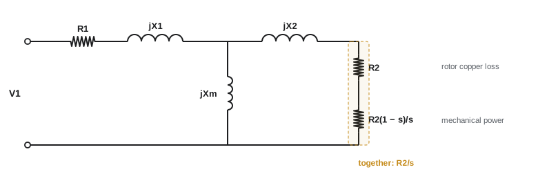
An induction motor is a transformer whose secondary rotates. Per phase, the stator has resistance \(R_1\) and leakage reactance \(X_1\); the magnetizing reactance \(X_m\) carries the current that sets up the air-gap flux (larger than in a transformer because of the air gap, typically 25 to 40% of rated current); and the rotor, referred to the stator, has leakage reactance \(X_2\) and an apparent resistance \(R_2/s\). Splitting \(R_2/s\) into \(R_2\) (rotor copper loss) and \(R_2(1-s)/s\) shows where the mechanical power comes from:
The air-gap power \(P_{ag}\) crosses from stator to rotor; a fraction \(s\) is lost as heat in the rotor and the rest becomes mechanical power. This is why induction motors must run at low slip to be efficient: at 3% slip, 3% of the air-gap power is wasted in the rotor. The torque equals air-gap power divided by synchronous angular speed.
Worked problem
Power flow
A motor has an air-gap power of 100 kW at a slip of 0.03. Stator copper loss is 2.5 kW, core loss 1.5 kW and friction and windage 1.0 kW. Find rotor copper loss, mechanical power, output and efficiency.
Show solution
- Rotor copper loss \(= 0.03 \times 100 = 3.0\) kW; developed mechanical power \(= 97.0\) kW.
- Output \(= 97.0 - 1.0 = 96.0\) kW.
- Input \(= 100 + 2.5 + 1.5 = 104.0\) kW; efficiency \(= 96.0/104.0 = 92.3\%\).
Answer: Rotor copper loss 3 kW, output 96 kW and efficiency 92.3%. The rotor loss alone is directly set by slip, so the slip of a motor at full load is a quick indicator of its efficiency.
The torque-speed curve
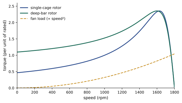
Solving the equivalent circuit at each slip gives the torque-speed curve. Starting from standstill, torque rises from the locked-rotor (starting) value to a maximum, the breakdown or pull-out torque, and then falls steeply to zero at synchronous speed. Normal operation is on the steep, nearly linear part of the curve near synchronous speed, where torque is roughly proportional to slip. If the load exceeds breakdown torque, the motor stalls. The slip at maximum torque is proportional to rotor resistance, while the maximum torque itself does not depend on rotor resistance:
where \(R_{th}\) and \(X_{th}\) are the Thevenin equivalent of the stator and magnetizing branch. Torque is proportional to the square of voltage, so a 10% voltage drop reduces starting and breakdown torque by 19%.
import numpy as np
from scipy.optimize import brentq

# 4160 V, 60 Hz, 4-pole, 500 hp induction motor; per-phase equivalent circuit (ohms, referred to stator)
VLL, f, poles = 4160.0, 60.0, 4
V = VLL / np.sqrt(3)
R1, X1, Xm, R2, X2 = 0.50, 4.0, 100.0, 0.80, 4.5
ns = 120 * f / poles                       # synchronous speed (rpm)
ws = 2 * np.pi * ns / 60
P_rated, P_fw = 373e3, 4e3                 # 500 hp output; friction and windage

def motor(s, deep):
    r2 = R2 * (1 + deep * s)               # deep rotor bars: resistance rises with rotor frequency
    Z2 = r2 / s + 1j * X2
    Z = R1 + 1j * X1 + (1j * Xm * Z2) / (1j * Xm + Z2)
    I1 = V / Z
    I2 = I1 * (1j * Xm) / (1j * Xm + Z2)
    Pag = 3 * abs(I2)**2 * r2 / s          # air-gap power
    Pmech = Pag * (1 - s)
    Pin = 3 * (V * np.conj(I1)).real
    return Pag / ws, abs(I1), Pmech, Pin, np.cos(np.angle(I1))

for deep, name in ((0.0, "single-cage rotor"), (1.5, "deep-bar rotor")):
    s_r = brentq(lambda s: motor(s, deep)[2] - P_rated - P_fw, 1e-4, 0.2)
    T, I, Pm, Pin, pf = motor(s_r, deep)
    Ts, Is, *_ = motor(1.0, deep)
    slips = np.linspace(0.001, 1, 20000)
    torques = np.array([motor(s, deep)[0] for s in slips])
    k = torques.argmax()
    print(name)
    print(f"   rated: slip {s_r:.4f}, {ns * (1 - s_r):.0f} rpm, {I:.1f} A, pf {pf:.3f},"
          f" efficiency {(Pm - P_fw) / Pin * 100:.1f}%, torque {T:.0f} N.m")
    print(f"   start: {Is:.0f} A ({Is / I:.1f} x rated), torque {Ts / T:.2f} x rated;"
f" breakdown {torques[k] / T:.2f} x rated at slip {slips[k]:.3f}")single-cage rotor rated: slip 0.0206, 1763 rpm, 64.1 A, pf 0.847, efficiency 95.4%, torque 2042 N.m start: 286 A (4.5 x rated), torque 0.47 x rated; breakdown 2.36 x rated at slip 0.096 deep-bar rotor rated: slip 0.0213, 1762 rpm, 64.1 A, pf 0.847, efficiency 95.3%, torque 2044 N.m start: 277 A (4.3 x rated), torque 1.10 x rated; breakdown 2.35 x rated at slip 0.112
The single-cage model runs at 1763 rpm (2.1% slip) at rated output, drawing 64 A at 0.85 power factor and 95.4% efficiency, with breakdown torque 2.36 times rated. Its starting torque is only 0.47 times rated, too low for many loads. Real squirrel-cage motors use deep or double-cage rotor bars: at standstill the rotor frequency is 60 Hz, so current crowds to the top of the bars (skin effect), raising the effective rotor resistance and therefore starting torque, while at running slip (about 1 Hz) the current spreads through the whole bar and resistance stays low. The simple model of this effect raises starting torque to 1.10 times rated with almost no change in full-load efficiency. Real motors also draw 5 to 7 times rated current at start, more than this model, because their leakage reactances fall when saturated by the large starting currents.
Worked problem
Effect of voltage on torque
A motor has a starting torque of 150% of rated at rated voltage. During starting, the supply voltage dips to 85%. What starting torque is available? Can it start a conveyor that needs 120% of rated torque to break away?
Show solution
- Torque scales with \(V^2\): \(150\% \times 0.85^2 = 108\%\).
Answer: Only 108% of rated torque is available, less than the 120% needed, so the motor will not start the loaded conveyor. Voltage dips during starting are a common cause of failure to start; the remedies include a stiffer supply, a motor with higher starting torque, or a soft starter or drive designed for high-torque starting.
Design classes
NEMA MG 1 defines design letters for squirrel-cage motors by their torque-speed shape:
| Design | Starting torque | Starting current | Full-load slip | Typical loads |
|---|---|---|---|---|
| A | Normal | High (unrestricted) | Low | Fans, pumps; high efficiency |
| B | Normal (about 150%) | Normal (about 6.5x) | 3–5% | General purpose; most common |
| C | High (about 250%) | Normal | 3–5% | Loaded conveyors, compressors |
| D | Very high (about 275%) | Low | 5–13% | Punch presses, hoists with flywheels |
IEC uses similar classes (N, H). Wound-rotor motors bring the rotor windings out through slip rings so external resistance can be added, giving high starting torque with low current, and were used for large hoists and mills before modern drives.
Starting methods
Direct-on-line (across-the-line) starting is simplest and gives full starting torque, but the starting current, 5 to 7 times rated, can cause voltage dips that disturb other loads and strain the supply. Alternatives reduce current at the cost of torque:
- Wye-delta starting: a delta-connected motor is started in wye, reducing phase voltage to \(1/\sqrt{3}\), and line current and torque to one third.
- Autotransformer starting: taps (typically 50, 65 and 80%) reduce voltage; line current and torque both scale with the square of the tap.
- Solid-state soft starters: thyristors ramp the voltage up, limiting current smoothly; torque falls with the square of voltage.
- Variable-frequency drives: start at low frequency and voltage, providing full torque at little more than rated current, the best performance but at the highest cost.
Worked problem
Reduced-voltage starting
A motor draws 6 times rated current and develops 150% of rated torque when started direct-on-line. Compare wye-delta starting and an autotransformer starter on the 65% tap.
Show solution
- Wye-delta: line current \(6/3 = 2.0\) times rated; torque \(150/3 = 50\%\).
- Autotransformer 65%: motor current \(6 \times 0.65 = 3.9\); line current \(3.9 \times 0.65 = 2.5\) times rated; torque \(150 \times 0.65^2 = 63\%\).
Answer: Wye-delta limits line current to 2 times rated but gives only 50% starting torque; the autotransformer at 65% gives 2.5 times current and 63% torque. Both suit fans and centrifugal pumps, which need little torque at low speed, but not loads that need high breakaway torque.
Speed control with variable-frequency drives
Since speed is close to synchronous speed, the practical way to vary it is to vary the supply frequency. A variable-frequency drive (VFD) rectifies the supply to a DC bus and uses an inverter of IGBTs switching at several kilohertz (pulse-width modulation) to synthesize three-phase voltage of variable frequency and magnitude. To keep the air-gap flux constant (Lesson 1), voltage is varied in proportion to frequency (constant V/f) up to rated frequency, giving rated torque capability at any speed below base speed. Above rated frequency, voltage cannot rise further, so flux weakens and the motor delivers constant power, just as with DC field weakening (Lesson 5). Vector (field-oriented) control goes further, controlling flux and torque currents independently to give DC-like dynamic performance.
For fans and centrifugal pumps, VFDs save large amounts of energy because, by the affinity laws, flow is proportional to speed while power is proportional to the cube of speed. Throttling a valve or damper to reduce flow wastes the energy that a slower fan would save.
Worked problem
Fan energy savings
A cooling fan motor draws 75 kW at full speed. A VFD reduces speed to 80% for 6000 hours a year. Estimate the power and annual energy savings, ignoring drive losses.
Show solution
- Power at 80% speed: \(75 \times 0.8^3 = 38.4\) kW.
- Saving: \(75 - 38.4 = 36.6\) kW; annual \(= 36.6 \times 6000 = 219{,}600\) kWh.
Answer: About 220 MWh a year, roughly half the fan's energy, from a 20% speed reduction. After allowing about 3% drive losses, the savings remain large, which is why VFDs on fans and pumps are among the most cost-effective efficiency measures in buildings and data centers (DCE-330).
VFDs introduce issues of their own: harmonic currents drawn from the supply (mitigated by multi-pulse rectifiers, filters or active front ends), fast voltage edges that stress motor insulation and cause reflected-wave overvoltages on long cables, and shaft voltages that drive bearing currents and damage bearings unless shaft grounding or insulated bearings are used. Motors intended for drives should be inverter-duty rated.
Efficiency standards and nameplate data
In the US, the Department of Energy sets minimum efficiencies for general-purpose motors from 1 to 500 hp under 10 CFR Part 431, at NEMA Premium (IE3) levels since 2016, tested to IEEE 112 Method B or CSA C390. Motors are commonly rated 460 V for 480 V systems (and 200 or 230 V for 208 and 240 V systems). The nameplate gives rated power, voltage, full-load current, speed, frequency, service factor, insulation class, design letter, code letter (locked-rotor kVA per hp) and nominal efficiency.
The service factor (often 1.15) indicates permissible continuous overload at rated voltage and frequency, at the cost of higher temperature and shorter insulation life. Insulation life roughly halves for every 10 °C rise above the rated temperature, so overloaded or poorly ventilated motors fail early.
Worked problem
Payback of a premium motor
A 50 hp (37.3 kW) pump motor runs 8000 hours a year at 75% load. Replacing a 91.7% efficient motor with a 94.5% efficient one costs $2,000 extra. At $0.10/kWh, what is the simple payback?
Show solution
- Output: \(37.3 \times 0.75 = 28.0\) kW.
- Input power: \(28.0/0.917 = 30.5\) kW versus \(28.0/0.945 = 29.6\) kW; saving 0.9 kW.
- Annual saving: \(0.9 \times 8000 \times 0.10 = \$720\); payback \(= 2000/720 = 2.8\) years.
Answer: About 2.8 years, and the motor lasts 15 to 20 years. Over its life, a motor's electricity typically costs 50 to 100 times its purchase price, which is why efficiency standards and lifecycle costing matter.
Protection
Article 430 of the National Electrical Code governs motor circuits. Branch-circuit conductors must be sized for at least 125% of the motor's full-load current from NEC tables (430.22, using Table 430.250 for three-phase motors rather than the nameplate), overload protection is generally set at not more than 125% of nameplate full-load current for motors with a service factor of 1.15 or more or a temperature rise of 40 °C or less, and 115% for others (430.32), and short-circuit and ground-fault protection is sized from Table 430.52 to allow starting while protecting the circuit. Motors also need a disconnecting means within sight (430.102), and drives must follow Part X of the article.
Beyond code minimums, larger motors use electronic motor protection relays that detect overload, phase loss and unbalance (a small voltage unbalance causes a much larger current unbalance and extra heating), locked rotor, ground faults and high winding temperature from embedded sensors.
Lesson 8 continues with starting dynamics, vector control, braking and induction generators, and Lesson 12 with testing and protection in practice.
Common mistakes
MistakeExpecting an induction motor to reach synchronous speed.
InsteadSlip is needed to induce rotor current and torque.
MistakeIgnoring the effect of voltage dips on starting.
InsteadTorque scales with V²; check starting under the expected voltage.
MistakeUsing wye-delta or soft starters on high-inertia or high-breakaway loads.
InsteadReduced-voltage starting cuts torque; use a VFD or a high-torque design.
MistakeRunning a standard motor on a VFD with long leads without checking insulation.
InsteadUse inverter-duty motors, filters and bearing protection.
MistakeSizing conductors from nameplate current.
InsteadUse NEC Table 430.250 for conductors and short-circuit protection; nameplate for overloads.
Summary and key terms
- Three-phase stator currents create a field rotating at ns = 120f/p.
- Slip s = (ns − n)/ns induces rotor current; full-load slip is 1–5%.
- Air-gap power splits into rotor copper loss sPag and mechanical power (1 − s)Pag; T = Pag/ωs.
- Torque-speed curves show starting, breakdown and running regions; torque scales with V².
- Deep-bar and double-cage rotors raise starting torque without sacrificing running efficiency.
- Wye-delta, autotransformer, soft starters and VFDs reduce starting current, with less torque except for VFDs.
- VFDs control speed with constant V/f; fan and pump power falls with speed cubed.
- DOE sets NEMA Premium efficiencies; NEC Article 430 sets conductor, overload and short-circuit protection.
- Synchronous speed
- The speed of the rotating field, 120f/p rpm.
- Slip
- The fractional difference between synchronous and rotor speed.
- Squirrel-cage rotor
- A rotor of bars shorted by end rings.
- Air-gap power
- Power transferred from stator to rotor across the air gap.
- Breakdown torque
- The maximum torque an induction motor can develop.
- Locked-rotor torque
- Torque at standstill with rated voltage applied.
- Deep-bar rotor
- A rotor whose bars use skin effect to raise starting resistance.
- NEMA design letter
- Classification of torque-speed characteristics (A, B, C, D).
- Variable-frequency drive
- A converter supplying variable-frequency, variable-voltage power.
- Affinity laws
- Fan and pump relations: flow ∝ speed, pressure ∝ speed², power ∝ speed³.
- Service factor
- Permissible continuous overload multiplier on the nameplate.
Practice problems
Work each problem on paper first, then reveal the answer to check.
Synchronous speed of an 8-pole, 60 Hz motor?
Show answer
900 rpm.
A 4-pole motor runs at 1746 rpm. Slip?
Show answer
54/1800 = 3%.
Air-gap power 50 kW at 4% slip. Rotor copper loss and developed power?
Show answer
2 kW and 48 kW.
Torque of a 4-pole, 60 Hz motor with 50 kW air-gap power?
Show answer
50,000/188.5 = 265 N·m.
Voltage drops to 90%. Effect on breakdown torque?
Show answer
It falls to 81%.
What does doubling rotor resistance do to the slip at maximum torque and to maximum torque?
Show answer
Doubles the slip; maximum torque is unchanged.
Direct-on-line start gives 6x current and 180% torque. Wye-delta values?
Show answer
2x line current, 60% torque.
A pump at 70% speed: fraction of full-speed power?
Show answer
0.7³ = 34%.
Why must V/f be held constant below base speed?
Show answer
To keep air-gap flux constant, avoiding saturation at low frequency and loss of torque.
Give two problems VFDs can cause.
Show answer
Supply harmonics, insulation stress from fast edges and reflections, bearing currents.
Lesson quiz · 5 questions
Score 60% or more to complete this lesson.
Create a free account to save your progress, take quizzes and earn a certificate.