
ELE-370 · Lesson 2 of 12 · 31 min
Electromechanical energy conversion
Lesson 1 showed how currents set up magnetic flux and how changing flux induces voltage. This lesson asks the question at the heart of every motor, generator, relay and solenoid: how does a magnetic field produce mechanical force, and how does mechanical motion produce electrical power? The answer comes from conservation of energy. By tracking the energy stored in the magnetic field as a device moves, we can calculate forces and torques for any geometry, explain why iron is pulled into a coil, and derive the two mechanisms of torque used by all rotating machines: reluctance torque and the interaction of two magnetic fields. The lesson ends with a simple way to size machines from the magnetic shear stress in the air gap, which explains why motors of the same torque have similar rotor volumes.
Energy balance in a lossless coupling field
Consider a coil wound on an iron structure with a movable part, such as the plunger of a solenoid. Electrical energy flows in through the coil terminals, mechanical energy flows out through the moving part, and some energy is stored in the magnetic field. If we set aside the resistance of the coil and the core losses as external losses, the remaining coupling field is lossless and conservative:
where \(\lambda = N\Phi\) is the flux linkage of the coil and \(x\) the position of the moving part. When the part is held still, all the electrical energy supplied goes into the field, so the stored energy at flux linkage \(\lambda\) is
the area between the \(\lambda\)-\(i\) curve and the \(\lambda\) axis. For a linear magnetic circuit, \(\lambda = L(x)\,i\), and the stored energy is \(W_{fld} = \lambda^2/(2L) = \tfrac{1}{2} L i^2\). Most of this energy is stored in the air gaps, not in the iron: a high-permeability core needs very little magnetizing force, so the energy density \(B^2/(2\mu)\) is small in iron and large in air.
Force from energy and co-energy
Rearranging the energy balance with flux linkage held constant (no electrical input during a small motion) shows that the mechanical work must come from the stored energy:
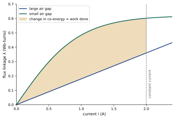
It is usually more convenient to work with current as the independent variable, because that is what a power supply controls. The co-energy is the area between the \(\lambda\)-\(i\) curve and the \(i\) axis,
and the force at constant current is
Both expressions give the same force at a given instant; they are two ways of computing one physical quantity. For a linear circuit, energy and co-energy are equal, and the force is
This result has a clear physical meaning: a magnetic system always pushes in the direction that increases its inductance, that is, reduces its reluctance. Iron is pulled into a coil, the plunger of a solenoid closes the air gap, and a rotor turns to align its iron with the field. The force does not depend on the direction of the current, because it depends on \(i^2\).
Force in terms of the air-gap flux density
For an air gap of area \(A\) carrying uniform flux density \(B\), the field energy in a gap of length \(g\) is \(\tfrac{B^2}{2\mu_0} A g\). Opening the gap by \(dg\) at constant flux adds energy \(\tfrac{B^2}{2\mu_0} A\, dg\), which must be supplied as mechanical work against an attractive force, so the force on each pole face is
This is the magnetic pressure: about 400 kPa (4 atmospheres) at 1 T and 1 MPa at 1.6 T, close to the saturation limit of electrical steel. It explains why lifting magnets can hold metric tons, and why the force of an electromagnet is limited by saturation however much current is supplied.
import numpy as np

# Plunger electromagnet (reluctance actuator): coil of N turns, iron path plus two air gaps of length g each.
mu0 = 4e-7 * np.pi
N, I = 800, 2.0                # turns, amperes
A = 4e-4                       # pole face area, m^2 (20 mm x 20 mm)
l_fe, mu_r = 0.12, 2000        # iron path length (m) and relative permeability

def flux_linkage(i, g):
    R = l_fe / (mu0 * mu_r * A) + 2 * g / (mu0 * A)     # total reluctance
    return N * N * i / R                                # lambda = L i, linear material

def coenergy(i, g):
    return 0.5 * flux_linkage(i, g) * i                 # W_co = (1/2) L i^2 for a linear circuit

for g_mm in (0.5, 1.0, 2.0, 4.0):
    g = g_mm / 1000
    dg = 1e-7
    F = (coenergy(I, g + dg) - coenergy(I, g - dg)) / (2 * dg)       # F = dW_co/dx at constant current
    B = flux_linkage(I, g) / (N * A)
    F_pole = 2 * B ** 2 * A / (2 * mu0)                              # two pole faces, B^2 A / (2 mu0) each
    L = flux_linkage(I, g) / I
    print(f"gap {g_mm:3.1f} mm: L = {L * 1000:6.1f} mH, B = {B:5.3f} T, force from co-energy {-F:6.1f} N, from B^2 A/(2 mu0) {F_pole:6.1f} N")
# The same actuator if the iron saturates near 1.6 T: force cannot keep rising as the gap closes
print(f"at 0.5 mm, B = {flux_linkage(I, 0.0005) / (N * A):.2f} T would exceed saturation (about 1.6 T): the real force is limited to about {2 * 1.6 ** 2 * A / (2 * mu0):.0f} N")gap 0.5 mm: L = 303.5 mH, B = 1.897 T, force from co-energy 1145.2 N, from B^2 A/(2 mu0) 1145.2 N gap 1.0 mm: L = 156.2 mH, B = 0.976 T, force from co-energy 303.2 N, from B^2 A/(2 mu0) 303.2 N gap 2.0 mm: L = 79.2 mH, B = 0.495 T, force from co-energy 78.1 N, from B^2 A/(2 mu0) 78.1 N gap 4.0 mm: L = 39.9 mH, B = 0.249 T, force from co-energy 19.8 N, from B^2 A/(2 mu0) 19.8 N at 0.5 mm, B = 1.90 T would exceed saturation (about 1.6 T): the real force is limited to about 815 N
The two methods agree exactly, as they must. Halving the gap from 2 mm to 1 mm almost quadruples the force, because the flux density doubles (the gaps dominate the reluctance) and force scales with \(B^2\). At 0.5 mm the linear model predicts 1.9 T, which electrical steel cannot reach without enormous magnetizing current; the real force levels off near the saturation value. Solenoid and contactor designers use this behavior: the pull-in force at a large gap must overcome the spring, while the holding force at a closed gap is far larger.
Worked problem
Holding force of a lifting magnet
A lifting magnet has two pole faces, each 100 mm × 200 mm, and drives 1.2 T through a thin air gap into a steel plate. What force can it exert, and what plate mass can it hold with a safety factor of 3?
Show solution
- Area per pole: \(A = 0.1 \times 0.2 = 0.02\) m².
- Force per pole: \(F = \frac{1.2^2 \times 0.02}{2 \times 4\pi \times 10^{-7}} = \frac{0.0288}{2.513 \times 10^{-6}} = 11{,}460\) N.
- Two poles: 22,900 N. With a safety factor of 3: 7,640 N, or \(7{,}640/9.81 = 779\) kg.
Answer: About 22.9 kN, enough to hold a plate of roughly 780 kg with a safety factor of 3. Rust, paint or a curved plate add air gap and reduce the force sharply, which is why lifting-magnet ratings assume clean, flat, thick steel.
Torque in rotating systems
For rotation, force becomes torque and position becomes angle \(\theta\):
Reluctance torque
A singly excited system with a rotor whose reluctance varies with angle, such as an iron bar between two poles, has inductance that varies with rotor position. A common approximation is \(L(\theta) = L_0 + L_2 \cos 2\theta\), largest when the bar is aligned with the poles. The torque
pulls the rotor toward alignment, where the inductance is greatest. Reluctance torque is the working principle of switched reluctance motors and synchronous reluctance motors (Lesson 11), stepper motors, and it adds to the torque of salient-pole synchronous machines (Lesson 10) and interior permanent magnet motors.
Mutual (alignment) torque
With two windings, one on the stator and one on the rotor, the co-energy for linear materials is
If the self-inductances do not vary with angle (a round rotor) and the mutual inductance varies as \(M(\theta) = M \cos\theta\), the torque is
The two windings behave like two magnets trying to align their fields. Torque is greatest when their axes are 90° apart and zero when aligned. All conventional rotating machines work this way: the stator and rotor each produce a magnetic field, and torque arises from the tendency of the fields to align. Expressed in terms of fields, the torque is proportional to the product of the stator and rotor field strengths and the sine of the angle between them:
where \(F_s\) and \(F_r\) are the stator and rotor magnetomotive forces and \(\delta\) is the angle between them. For steady torque the two fields must be stationary relative to each other. This single requirement explains the main machine types:
| Machine | Stator field | Rotor field | How the fields stay aligned |
|---|---|---|---|
| DC machine (Lesson 5) | stationary, from field poles | stationary in space | the commutator switches rotor coils so the armature field stays at 90° to the poles |
| Synchronous machine (Lesson 9) | rotating at synchronous speed | fixed to the rotor (DC field or magnets) | the rotor turns at exactly synchronous speed |
| Induction machine (Lesson 7) | rotating at synchronous speed | induced currents at slip frequency | rotor currents at slip frequency produce a field rotating at synchronous speed relative to the stator |
| Brushless PM machine (Lesson 11) | switched or rotated by an inverter | fixed to the rotor (magnets) | the inverter uses rotor position to keep the stator field ahead of the rotor |
Motional EMF and the Blv and Bil relations
A second, more direct view of the same physics uses forces on conductors. A conductor of length \(l\) carrying current \(i\) in a field \(B\) perpendicular to it experiences a force \(F = Bil\) (the Lorentz force), and a conductor moving at velocity \(v\) through the field has a motional EMF \(e = Blv\). Multiplying the two gives \(e\,i = Bliv = Fv\): the electrical power absorbed equals the mechanical power produced. These relations give quick estimates for machines with conductors in an air gap, such as DC machines, and show that every motor is also a generator. A motor's rotating conductors generate a back EMF opposing the supply, which is why a motor draws large current at standstill, when there is no back EMF, and less as it speeds up.
Worked problem
Force and EMF on a conductor
A rotor conductor 0.3 m long lies in an air-gap field of 0.8 T and carries 200 A. The rotor radius is 0.1 m and it turns at 1,800 rpm. Find the force, the torque contribution, the EMF, and check the power balance.
Show solution
- Force: \(F = Bil = 0.8 \times 200 \times 0.3 = 48\) N. Torque: \(48 \times 0.1 = 4.8\) N·m.
- Surface speed: \(v = \omega r = (1{,}800 \times 2\pi/60) \times 0.1 = 18.85\) m/s.
- EMF: \(e = Blv = 0.8 \times 0.3 \times 18.85 = 4.52\) V.
- Power: \(e\,i = 4.52 \times 200 = 905\) W; \(T\omega = 4.8 \times 188.5 = 905\) W.
Answer: Each conductor contributes 4.8 N·m and 4.52 V, and the electrical and mechanical powers match at 905 W, as conservation of energy requires.
Sizing machines from air-gap shear stress
The tangential force per unit area of rotor surface, the air-gap shear stress \(\sigma\), is limited by the flux density the iron can carry and the current density the conductors can carry before overheating. The torque of a rotor of diameter \(D\) and length \(L\) is the force on its surface times its radius:
So torque is proportional to rotor volume. Typical shear stresses are 5 to 15 kPa for small totally enclosed fan-cooled motors, 15 to 35 kPa for large industrial machines, and 40 to 100 kPa for liquid-cooled high-performance machines such as electric vehicle and aircraft motors.
import numpy as np

# Sizing rotating machines from air-gap shear stress: T = 2 sigma (pi r^2 L) = sigma x 2 x rotor volume
def torque(sigma, D, L):
    return sigma * np.pi * D ** 2 * L / 2

machines = [
    ("1.5 kW totally enclosed fan-cooled induction motor", 10e3, 0.080, 0.090, 1750),
    ("75 kW industrial induction motor", 20e3, 0.230, 0.250, 1780),
    ("150 kW EV traction PM motor (liquid cooled)", 50e3, 0.150, 0.150, 6000),
    ("3 MW wind generator, direct drive", 45e3, 5.0, 1.2, 14),
]
for name, sigma, D, L, rpm in machines:
    T = torque(sigma, D, L)
    P = T * rpm * 2 * np.pi / 60
    print(f"{name}: shear {sigma / 1000:.0f} kPa, rotor {D * 1000:.0f} x {L * 1000:.0f} mm -> torque {T:9.0f} N m, {P / 1000:7.1f} kW at {rpm} rpm")
# Rotor volume needed for a given torque at a given shear stress
for T_req in (100, 1000, 10000):
    V = T_req / (2 * 25e3)
print(f"{T_req:6d} N m at 25 kPa needs rotor volume {V * 1000:6.2f} L (for L = D: D = {(4 * V / np.pi) ** (1 / 3) * 1000:.0f} mm)")1.5 kW totally enclosed fan-cooled induction motor: shear 10 kPa, rotor 80 x 90 mm -> torque 9 N m, 1.7 kW at 1750 rpm 75 kW industrial induction motor: shear 20 kPa, rotor 230 x 250 mm -> torque 415 N m, 77.4 kW at 1780 rpm 150 kW EV traction PM motor (liquid cooled): shear 50 kPa, rotor 150 x 150 mm -> torque 265 N m, 166.5 kW at 6000 rpm 3 MW wind generator, direct drive: shear 45 kPa, rotor 5000 x 1200 mm -> torque 2120575 N m, 3108.9 kW at 14 rpm 100 N m at 25 kPa needs rotor volume 2.00 L (for L = D: D = 137 mm) 1000 N m at 25 kPa needs rotor volume 20.00 L (for L = D: D = 294 mm) 10000 N m at 25 kPa needs rotor volume 200.00 L (for L = D: D = 634 mm)
The estimates are close to real machines of these ratings, given that shear stress varies with cooling and design. Two practical consequences follow. First, a motor's size and cost are set mainly by its torque, not its power: a 75 kW motor at 1,800 rpm is about twice the size of a 75 kW motor at 3,600 rpm. This is why traction motors run at high speed through a gearbox, and why a direct-drive wind generator turning at 14 rpm needs a rotor about 5 m across. Second, raising the shear stress through better cooling (liquid jackets, direct conductor cooling) or stronger magnets shrinks the machine, which matters most where weight is critical.
Losses and efficiency in energy conversion
Real machines lose energy in the windings (\(I^2R\) copper losses), in the core (hysteresis and eddy currents, Lesson 1), in friction and windage, and in stray load losses from leakage fields and harmonics. Efficiency is \(\eta = P_{out}/P_{in} = P_{out}/(P_{out} + \text{losses})\). Because losses are a few percent of the power converted, large machines are very efficient: large transformers exceed 99.5%, large generators 98.5%, and industrial motors of a few hundred kilowatts about 96%. Small machines are less efficient because their losses do not scale down as quickly as their power: a 100 W fan motor may be only 50 to 70% efficient. Lost energy becomes heat, which must be removed, and temperature rise ultimately limits the rating of every machine (Lesson 12).
Common mistakes
MistakeTaking the derivative of stored energy at constant current to find force.
InsteadUse energy at constant flux linkage (with a minus sign) or co-energy at constant current.
MistakeExpecting electromagnet force to keep rising as the gap closes.
InsteadSaturation limits the flux density and hence the force near \(B_{sat}^2 A/(2\mu_0)\).
MistakeThinking reversing the current reverses a reluctance force.
InsteadReluctance force depends on \(i^2\) and always acts to increase inductance.
MistakeSizing a machine by its power rating alone.
InsteadSize depends mainly on torque: rotor volume is proportional to torque.
MistakeAssuming steady torque is possible with fields moving relative to each other.
InsteadStator and rotor fields must be stationary relative to each other.
Summary and key terms
- Electrical energy in equals field energy stored plus mechanical work out, for a lossless coupling field.
- Force is the negative derivative of field energy at constant flux linkage, or the derivative of co-energy at constant current.
- For linear systems, \(F = \tfrac{1}{2} i^2\, dL/dx\): magnetic systems move to increase inductance.
- Magnetic pressure \(B^2/(2\mu_0)\) limits electromagnet force, with saturation setting the maximum.
- Rotating machines produce reluctance torque and mutual torque, \(T = k F_s F_r \sin\delta\), with fields stationary relative to each other.
- Torque is proportional to rotor volume and air-gap shear stress, so machine size follows torque.
- Coupling field
- The magnetic field through which electrical and mechanical energy are exchanged.
- Flux linkage
- The product of turns and flux linking a coil, \(\lambda = N\Phi\).
- Field energy
- Energy stored in the magnetic field, the area to the left of the λ-i curve.
- Co-energy
- The area below the λ-i curve, \(\lambda i - W_{fld}\).
- Magnetic pressure
- The force per unit area on a pole face, \(B^2/(2\mu_0)\).
- Reluctance torque
- Torque arising from rotor position-dependent inductance.
- Mutual torque
- Torque from the interaction of two windings or fields.
- Torque angle
- The angle between the stator and rotor fields.
- Motional EMF
- Voltage induced in a conductor moving through a field, \(e = Blv\).
- Air-gap shear stress
- Tangential force per unit rotor surface area.
Practice problems
Work each problem on paper first, then reveal the answer to check.
Force on a pole face of 0.01 m² at 1.0 T?
Show answer
\(1^2 \times 0.01/(2 \times 4\pi \times 10^{-7}) = 3{,}980\) N.
Inductance rises from 50 mH to 60 mH over 2 mm of travel at 3 A. Average force?
Show answer
\(\tfrac{1}{2} \times 9 \times 0.01/0.002 = 22.5\) N.
Which way does a reluctance force act?
Show answer
Toward increasing inductance (decreasing reluctance).
Field energy of a 0.2 H coil at 5 A?
Show answer
\(\tfrac{1}{2} \times 0.2 \times 25 = 2.5\) J.
At what torque angle is mutual torque greatest?
Show answer
90°.
EMF of a 0.5 m conductor moving at 20 m/s in 0.9 T?
Show answer
9 V.
Torque from a rotor 0.2 m diameter and 0.2 m long at 20 kPa?
Show answer
\(20{,}000 \times \pi \times 0.04 \times 0.2/2 = 251\) N·m.
Why do traction motors run at high speed?
Show answer
Size follows torque, so high speed gives more power from a smaller machine.
Where is most magnetic energy stored in a gapped core?
Show answer
In the air gap.
Efficiency of a machine with 50 kW output and 2 kW losses?
Show answer
50/52 = 96.2%.
Lesson quiz · 5 questions
Score 60% or more to complete this lesson.
Create a free account to save your progress, take quizzes and earn a certificate.