
ELE-370 · Lesson 3 of 12 · 35 min
Transformers
Transformers make the AC power system possible. By stepping voltage up for transmission and down for use, they let power travel hundreds of kilometers with low losses, then serve loads at safe voltages. A typical kilowatt-hour passes through four or five transformers between generator and outlet, so even small inefficiencies add up: transformers account for a significant share of all transmission and distribution losses. This lesson develops the ideal transformer, the practical equivalent circuit and how its parameters are measured, then voltage regulation, efficiency, per-unit values, three-phase connections, autotransformers, inrush and the regulations that govern transformer efficiency and protection.
The ideal transformer
A transformer consists of two or more windings on a common laminated core. An alternating voltage on the primary drives a magnetizing current that sets up an alternating flux; the flux links the secondary and induces a voltage in it (Faraday's law, Lesson 1). In an ideal transformer, with no losses, no leakage flux and infinite core permeability:
Voltage scales with the turns ratio, current inversely, and power in equals power out. An impedance \(Z_2\) connected to the secondary appears from the primary as \(a^2 Z_2\), which is why transformers are used for impedance matching and why secondary quantities can be "referred" to the primary side by multiplying impedances by \(a^2\), voltages by \(a\) and currents by \(1/a\).
Dot convention marks winding terminals with the same instantaneous polarity: current entering the dotted primary terminal corresponds to current leaving the dotted secondary terminal. Polarity matters when transformers are paralleled or connected in three-phase banks; North American distribution transformers are marked as additive or subtractive polarity.
Worked problem
Referring an impedance
A 2400/240 V transformer supplies a load of \(1.2 + j0.9\ \Omega\) on its secondary. What impedance does the 2400 V source see, and what is the primary current at rated secondary voltage?
Show solution
- \(a = 10\); referred impedance \(= 100 \times (1.2 + j0.9) = 120 + j90\ \Omega\), magnitude 150 \(\Omega\).
- Primary current \(= 2400/150 = 16\) A; secondary current \(= 240/1.5 = 160\) A \(= 10 \times 16\).
Answer: The source sees \(120 + j90\ \Omega\) and supplies 16 A, one tenth of the 160 A load current, with the same 38.4 kVA on both sides.
The practical transformer
A real transformer departs from the ideal in four ways, each represented in the equivalent circuit:
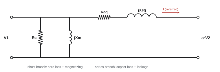
- Winding resistance \(R_1\), \(R_2\): copper (I²R) losses that grow with the square of load.
- Leakage reactance \(X_1\), \(X_2\): some flux links only one winding, causing voltage drops proportional to load current.
- Magnetizing reactance \(X_m\): the finite core permeability requires a magnetizing current to set up the flux, typically 1 to 5% of rated current.
- Core-loss resistance \(R_c\): represents hysteresis and eddy-current losses, which depend on voltage, not load.
Referring all quantities to one side and moving the shunt branch to the terminals (an approximation that introduces little error because magnetizing current is small) gives the approximate equivalent circuit, with a series impedance \(R_{eq} + jX_{eq}\) and a shunt branch of \(R_c\) in parallel with \(X_m\).
Measuring the parameters
The equivalent circuit parameters are found from two standard tests:
- Open-circuit test: rated voltage is applied to one winding (usually the low-voltage side for safety and convenience) with the other open. The current is the small no-load current, and the power is almost entirely core loss. From \(V_{oc}\), \(I_{oc}\) and \(P_{oc}\): \(R_c = V_{oc}^2/P_{oc}\), \(|Y| = I_{oc}/V_{oc}\), and \(X_m\) from the reactive part of the admittance.
- Short-circuit test: one winding (usually the high-voltage side) is supplied with a reduced voltage, just enough to circulate rated current, while the other is shorted. The voltage is small, so core loss is negligible, and the power is the copper loss at rated current. \(|Z_{eq}| = V_{sc}/I_{sc}\), \(R_{eq} = P_{sc}/I_{sc}^2\), and \(X_{eq} = \sqrt{|Z_{eq}|^2 - R_{eq}^2}\).
The short-circuit voltage as a percentage of rated voltage is the transformer's percent impedance (%Z), printed on its nameplate and used to calculate fault currents (ELE-380, ELEC-210).
import numpy as np

S, V1, V2 = 50e3, 2400.0, 240.0          # rating (VA), HV and LV voltages
a = V1 / V2
# open-circuit test on the LV side, short-circuit test on the HV side
Voc, Ioc, Poc = 240.0, 3.2, 230.0
Vsc, Isc, Psc = 55.0, 20.8, 620.0

# shunt branch (referred to LV), then to HV
Rc = Voc**2 / Poc
Ym = Ioc / Voc
Bm = np.sqrt(Ym**2 - (1 / Rc)**2)
Xm = 1 / Bm
# series branch (referred to HV)
Zeq = Vsc / Isc
Req = Psc / Isc**2
Xeq = np.sqrt(Zeq**2 - Req**2)
print(f"Rc = {Rc:.0f} ohm, Xm = {Xm:.1f} ohm (LV side)")
print(f"Req = {Req:.2f} ohm, Xeq = {Xeq:.2f} ohm (HV side);  per unit: R = {Req / (V1**2 / S):.4f}, X = {Xeq / (V1**2 / S):.4f}")

I_rated = S / V1
def regulation(pf, lag=True):
    I = I_rated * (pf - 1j * np.sqrt(1 - pf**2) * (1 if lag else -1))
    Vs = V1 + I * (Req + 1j * Xeq)                 # sending voltage needed for rated output voltage
    return (abs(Vs) - V1) / V1

for pf, lag in ((1.0, True), (0.8, True), (0.8, False)):
    kind = "unity" if pf == 1 else ("lagging" if lag else "leading")
    print(f"regulation at full load, pf {pf} {kind}: {regulation(pf, lag) * 100:+.2f}%")

Pcu_fl = I_rated**2 * Req
print(f"full-load copper loss {Pcu_fl:.0f} W, core loss {Poc:.0f} W")
for x in (0.25, 0.5, np.sqrt(Poc / Pcu_fl), 0.75, 1.0):
    out = x * S * 0.85
    eff = out / (out + Poc + x**2 * Pcu_fl)
print(f"load {x:5.0%}, pf 0.85: efficiency {eff * 100:.2f}%")Rc = 250 ohm, Xm = 78.6 ohm (LV side) Req = 1.43 ohm, Xeq = 2.22 ohm (HV side); per unit: R = 0.0124, X = 0.0193 regulation at full load, pf 1.0 unity: +1.26% regulation at full load, pf 0.8 lagging: +2.16% regulation at full load, pf 0.8 leading: -0.14% full-load copper loss 622 W, core loss 230 W load 25%, pf 0.85: efficiency 97.53% load 50%, pf 0.85: efficiency 98.22% load 61%, pf 0.85: efficiency 98.25% load 75%, pf 0.85: efficiency 98.21% load 100%, pf 0.85: efficiency 98.03%
The 50 kVA transformer has a per-unit series resistance of 0.0124 and reactance of 0.0193, so its impedance is about 2.3%: a short circuit on its secondary would draw about 1/0.023, or 43 times rated current. The magnetizing reactance seen from the low-voltage side is 78.6 \(\Omega\), drawing about 3 A at 240 V, under 2% of the 208 A rated low-voltage current.
Voltage regulation
As load current flows through the series impedance, the secondary voltage changes. Voltage regulation compares the no-load and full-load secondary voltages:
Using the equivalent circuit, the sending voltage needed to hold rated voltage at the load is \(\mathbf{V}_1 = \mathbf{V}_2^{\prime} + \mathbf{I}(R_{eq} + jX_{eq})\), and regulation is \((|V_1| - V_2^{\prime})/V_2^{\prime}\). A useful approximation is:
with \(+\) for lagging and \(-\) for leading power factor. The simulation shows regulation of 1.26% at unity power factor, 2.16% at 0.8 lagging, and \(-0.14\%\) at 0.8 leading: with leading current, the voltage rises with load, because the capacitive current flowing through the leakage reactance raises the secondary voltage.
Worked problem
Regulation by the approximate formula
A transformer has \(r = 0.012\) and \(x = 0.05\) per unit. Estimate its regulation at full load and 0.85 power factor lagging.
Show solution
- \(\cos\theta = 0.85\), \(\sin\theta = 0.527\).
- VR \(\approx 1.0 \times (0.012 \times 0.85 + 0.05 \times 0.527) = 0.0102 + 0.0264 = 0.0366\).
Answer: About 3.7%. Leakage reactance dominates regulation at typical lagging power factors, which is why larger transformers with higher reactance (chosen to limit fault current) have poorer regulation and often use tap changers to compensate.
Efficiency
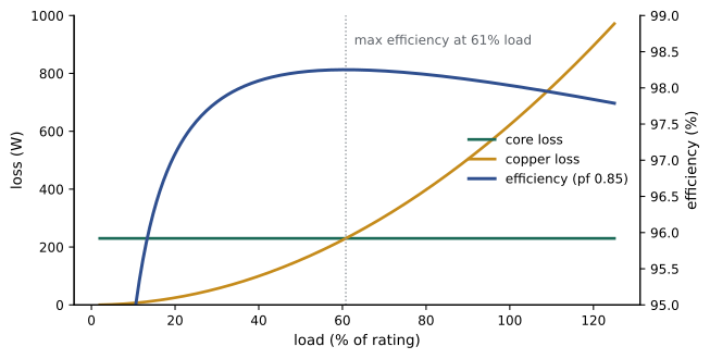
Transformer losses are the constant core loss \(P_{core}\) and the copper loss, which scales with the square of the load fraction \(x\) (output as a fraction of rating):
Efficiency is highest when copper loss equals core loss, at a load fraction of \(x = \sqrt{P_{core}/P_{cu,fl}}\). Distribution transformers, which are lightly loaded most of the time, are designed with low core loss so that maximum efficiency occurs around 35 to 50% load; power transformers that run near full load are designed for maximum efficiency closer to rating.
The 50 kVA example peaks at 98.25% efficiency at 61% load (where 230 W of core loss equals the copper loss) and is above 97.5% from 25% to full load. Because energy matters more than peak efficiency, utilities evaluate transformers by total owning cost: purchase price plus the present value of losses, with core loss weighted heavily because it occurs every hour of the year.
Worked problem
All-day efficiency
The 50 kVA transformer (core loss 230 W, full-load copper loss 622 W) serves a load of 40 kW at 0.85 pf (94% load) for 6 hours a day and 10 kW at 0.85 pf (24% load) for the remaining 18 hours. Compute the daily energy efficiency.
Show solution
- Output: \(40 \times 6 + 10 \times 18 = 420\) kWh.
- Core loss: \(0.230 \times 24 = 5.52\) kWh.
- Copper loss: \(0.622 \times (0.941^2 \times 6 + 0.235^2 \times 18) = 0.622 \times (5.31 + 0.99) = 3.92\) kWh.
- Efficiency \(= 420/(420 + 5.52 + 3.92) = 97.8\%\).
Answer: The all-day efficiency is 97.8%, lower than the 98% at full load, because core loss continues through the long lightly-loaded period. Over a year the transformer loses about 3,400 kWh, which is why low-core-loss designs pay back on lightly loaded units.
Per-unit values
Expressing transformer quantities in per unit (ELE-380) on the transformer's own rating makes them independent of which side they are referred to, and makes transformers of different sizes comparable. Series impedances of distribution transformers are typically 2 to 6%, and of large power transformers 8 to 15%. Magnetizing current is typically 0.5 to 3%. The per-unit impedance gives the available fault current directly: a transformer with 5% impedance on an infinite source supplies 20 times its rated current into a bolted fault.
Worked problem
Fault current from percent impedance
A 1500 kVA, 12.47 kV to 480Y/277 V transformer has 5.75% impedance. Estimate the maximum three-phase fault current at its secondary terminals, assuming an infinite source.
Show solution
- Rated secondary current: \(1{,}500{,}000/(\sqrt3 \times 480) = 1804\) A.
- Fault current \(= 1804/0.0575 = 31{,}400\) A.
Answer: About 31 kA, which sets the minimum interrupting rating of the downstream switchgear. Real fault current is somewhat lower because of source and cable impedance, and motor contribution adds to it.
Three-phase transformers
Three-phase power is transformed by three single-phase units in a bank or by a single three-phase transformer on a common core, which is cheaper, smaller and more efficient. The windings can be connected in wye (Y) or delta (Δ):
- Y-Y: simple, but third-harmonic currents and unbalanced loads cause problems unless the neutrals are grounded and a tertiary delta winding is provided.
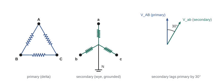
- Δ-Y: the most common step-down connection for distribution to commercial and industrial loads; the delta primary circulates triplen harmonics, and the wye secondary provides a grounded neutral for line-to-neutral loads. It introduces a 30° phase shift between primary and secondary.
- Y-Δ: common for generator step-up transformers (with the delta on the generator side) and step-down to motor loads.
- Δ-Δ: allows open-delta operation with one transformer removed at 57.7% of the bank capacity.
Phase shifts must match when transformers are paralleled; standards define the phase displacement (in North America, the low-voltage side lags the high-voltage side by 30° for Δ-Y and Y-Δ units).
Autotransformers, instrument transformers and inrush
An autotransformer has a single winding with a tap, so part of the winding is common to both circuits. Only part of the power is transformed magnetically; the rest is conducted directly. For ratios close to 1, an autotransformer is much smaller, cheaper and more efficient than a two-winding transformer of the same rating, so autotransformers are used to interconnect transmission voltages (for example 230/138 kV) and in motor starters and buck-boost applications. Their disadvantage is that the windings are not electrically isolated.
Instrument transformers scale currents and voltages for meters and relays: current transformers (CTs) produce a secondary current, typically 5 A or 1 A, proportional to line current, and voltage transformers (VTs) produce about 120 V. A CT secondary must never be open-circuited while the primary carries current, because the full primary mmf would then drive the core into saturation and produce dangerous voltages (ELEC-210).
When a transformer is energized, the flux may need to start from a value offset from its steady-state waveform, depending on the point on the voltage wave and the residual flux in the core. The flux can then peak at up to twice its normal value plus the remanence, deeply saturating the core and drawing an inrush current of 8 to 15 times rated current for a few cycles, decaying over seconds. Protective relays must distinguish inrush from faults, typically by its high second-harmonic content, and fuses and breakers must be chosen to ride through it.
Worked problem
Autotransformer rating
A 230/138 kV autotransformer supplies 300 MVA. What power is transformed magnetically?
Show solution
- \(S_{transformed} = 300 \times (1 - 138/230) = 300 \times 0.4 = 120\) MVA.
Answer: Only 120 MVA passes through the magnetic coupling; the other 180 MVA is conducted. The autotransformer needs core and winding sized for about 40% of a 300 MVA two-winding unit, which is why autotransformers are standard for interconnecting nearby transmission voltages.
Efficiency rules and protection in the US
Distribution transformers sold in the US must meet minimum efficiencies set by the Department of Energy under 10 CFR Part 431, specified at a reference load (50% for most distribution transformers, 35% for low-voltage dry-type). DOE adopted stricter standards in 2024, taking effect in 2029, that push many designs toward amorphous or improved grain-oriented steel cores. NEC Article 450 sets transformer overcurrent protection: Table 450.3(A) for transformers over 1000 V and Table 450.3(B) for those 1000 V and under, where primary-only protection is limited to 125% of rated primary current (or the next standard size), and primary protection up to 250% is allowed when secondary protection at 125% is provided. Article 450 also covers ventilation, working space and vaults.
Lesson 4 follows transformers into service: vector groups, parallel operation, tap changers, harmonic loads, thermal loading and condition assessment.
Common mistakes
MistakeReferring impedances with the turns ratio instead of its square.
InsteadImpedances refer by a², voltages by a, currents by 1/a.
MistakeDoing the open-circuit test on the high-voltage side without need.
InsteadUse the low-voltage side for the open-circuit test and the high-voltage side for the short-circuit test.
MistakeAssuming maximum efficiency occurs at full load.
InsteadIt occurs where copper loss equals core loss, often well below full load.
MistakeParalleling transformers with different phase shifts or impedances.
InsteadMatch voltage ratio, phase displacement, polarity and per-unit impedance.
MistakeOpen-circuiting an energized CT secondary.
InsteadShort the CT secondary before disconnecting instruments.
Summary and key terms
- An ideal transformer scales voltage by the turns ratio a, current by 1/a, and impedance by a².
- The equivalent circuit adds winding resistance, leakage reactance, magnetizing reactance and core-loss resistance.
- Open-circuit tests give core loss and the shunt branch; short-circuit tests give copper loss and the series impedance.
- Regulation depends on load, power factor and series impedance; leading loads can raise voltage.
- Efficiency peaks where copper loss equals core loss; all-day efficiency weights core loss heavily.
- Per-unit impedance gives fault current directly: I_fault = I_rated / Z_pu.
- Three-phase transformers use Y and Δ connections; Δ-Y introduces a 30° phase shift.
- DOE 10 CFR 431 sets minimum efficiencies; NEC 450.3 sets transformer overcurrent protection.
- Turns ratio
- The ratio of primary to secondary turns, a = N1/N2.
- Referred impedance
- An impedance expressed on the other side of a transformer by multiplying by a².
- Leakage reactance
- Reactance from flux that links only one winding.
- Magnetizing current
- The current needed to set up the core flux.
- Open-circuit test
- A test at rated voltage with the other winding open, measuring core loss.
- Short-circuit test
- A test at rated current with the other winding shorted, measuring copper loss and impedance.
- Voltage regulation
- The change in secondary voltage from no load to full load as a percentage.
- Percent impedance
- The short-circuit test voltage as a percentage of rated voltage.
- All-day efficiency
- Energy output divided by energy input over a day.
- Autotransformer
- A transformer with a winding common to both circuits.
- Inrush current
- The large transient magnetizing current when a transformer is energized.
Practice problems
Work each problem on paper first, then reveal the answer to check.
A 4160/480 V transformer supplies a 2 Ω load. What impedance does the primary see?
Show answer
a = 8.667; 75.1 × 2 = 150 Ω.
Open-circuit test: 480 V, 2.5 A, 300 W. Find Rc and Xm.
Show answer
Rc = 768 Ω; |Y| = 0.00521 S; G = 0.0013 S; B = 0.00504 S; Xm = 198 Ω.
Short-circuit test: 150 V, 40 A, 1200 W. Find Req and Xeq.
Show answer
Zeq = 3.75 Ω; Req = 0.75 Ω; Xeq = 3.67 Ω.
r = 0.01, x = 0.06 pu. Approximate regulation at full load, unity pf?
Show answer
About 1%.
Core loss 400 W, full-load copper loss 1600 W. Load fraction for maximum efficiency?
Show answer
√(400/1600) = 0.5.
A 75 kVA transformer at 80% load, unity pf, core loss 300 W, full-load copper loss 1100 W. Efficiency?
Show answer
60,000/(60,000 + 300 + 704) = 98.4%.
A 500 kVA transformer at 480 V with 5% impedance. Infinite-source fault current?
Show answer
601 A/0.05 = 12.0 kA.
Phase shift of a standard North American Δ-Y transformer?
Show answer
The low-voltage side lags the high-voltage side by 30°.
A 480/416 V autotransformer supplies 100 kVA. Power transformed?
Show answer
100 × (1 − 416/480) = 13.3 kVA.
How do relays distinguish inrush from faults?
Show answer
Inrush has high second-harmonic content; restraint blocks tripping.
Lesson quiz · 5 questions
Score 60% or more to complete this lesson.
Create a free account to save your progress, take quizzes and earn a certificate.