
ELE-370 · Lesson 12 of 12 · 31 min
Machine ratings, testing, maintenance and protection
The earlier lessons explained how electric machines work and how to calculate their performance. This final lesson turns to the practical knowledge that keeps machines running for decades: how temperature and insulation set a machine's rating, how machines are tested at the factory and in the field, how condition monitoring detects failures before they happen, how motors are protected, and how all of this comes together when an engineer specifies a motor and drive for a real application. Most motor failures are caused by bearings (about 40 to 50%) and stator winding insulation (about 30 to 35%), with rotor faults and other causes making up the rest, and both of the leading causes are strongly linked to temperature, contamination and the quality of installation and maintenance.
Temperature, insulation and rating
The output of a machine is limited by the temperature its insulation can withstand. Insulation systems are classified by their thermal class, the temperature at which they are expected to give a reasonable life:
| Thermal class | Maximum temperature | Allowable rise over 40 °C ambient (by resistance, motors) | Typical use |
|---|---|---|---|
| A (105) | 105 °C | 60 K | small older motors, rarely now |
| B (130) | 130 °C | 80 K | rise limit used in many industrial motors |
| F (155) | 155 °C | 105 K | standard insulation in modern motors |
| H (180) | 180 °C | 125 K | high-temperature, traction, dry-type transformers |
A common practice is to build motors with Class F insulation but limit the temperature rise to Class B values at rated load, leaving 25 K of thermal margin that extends life and allows the service factor overload. Insulation aging is a chemical process that roughly follows the Arrhenius law; as a rule of thumb, life halves for every 10 K increase in temperature (the transformer paper of Lesson 4 is more sensitive, halving every 6 to 7 K).
import numpy as np

# Insulation life versus hot-spot temperature (10 degree rule) for a Class F system used at Class B rise
classes = {"A": 105, "B": 130, "F": 155, "H": 180}
for T in (125, 135, 145, 155, 165, 175):
    rel = 2 ** ((classes["F"] - T) / 10)
    print(f"Class F insulation at {T} C hot spot: life {rel:5.2f} times that at its 155 C limit")

# First-order thermal model of a motor winding: temperature rise follows the square of current
tau = 30 * 60                                     # thermal time constant, s (running)
rise_rated = 80.0                                 # K at rated current (Class B rise)
amb = 40.0
def time_to_limit(I_pu, limit=155.0):
    final = amb + rise_rated * I_pu ** 2
    if final <= limit:
        return None, final
    t = -tau * np.log(1 - (limit - amb - rise_rated) / (final - amb - rise_rated))   # starting from rated temperature
    return t, final

for I_pu in (1.0, 1.15, 1.25, 1.5, 2.0):
    t, final = time_to_limit(I_pu)
    msg = f"settles at {final:.0f} C (within Class F)" if t is None else f"reaches 155 C after {t / 60:5.1f} min (would settle at {final:.0f} C)"
    print(f"load current {I_pu:.2f} pu from rated temperature: {msg}")

# Overload relay trip classes: trip time at 600% current
for cls in (10, 20, 30):
print(f"Class {cls} overload relay: trips within {cls} s at 6 x full-load current")Class F insulation at 125 C hot spot: life 8.00 times that at its 155 C limit Class F insulation at 135 C hot spot: life 4.00 times that at its 155 C limit Class F insulation at 145 C hot spot: life 2.00 times that at its 155 C limit Class F insulation at 155 C hot spot: life 1.00 times that at its 155 C limit Class F insulation at 165 C hot spot: life 0.50 times that at its 155 C limit Class F insulation at 175 C hot spot: life 0.25 times that at its 155 C limit load current 1.00 pu from rated temperature: settles at 120 C (within Class F) load current 1.15 pu from rated temperature: settles at 146 C (within Class F) load current 1.25 pu from rated temperature: reaches 155 C after 45.1 min (would settle at 165 C) load current 1.50 pu from rated temperature: reaches 155 C after 12.9 min (would settle at 220 C) load current 2.00 pu from rated temperature: reaches 155 C after 4.7 min (would settle at 360 C) Class 10 overload relay: trips within 10 s at 6 x full-load current Class 20 overload relay: trips within 20 s at 6 x full-load current Class 30 overload relay: trips within 30 s at 6 x full-load current
Running 20 K cooler quadruples insulation life, which is why the margin between Class B rise and Class F capability is so valuable, and why blocked cooling fins, high ambient temperatures, high altitude (thinner air cools less; derate above 1,000 m), low voltage, unbalance and harmonics all shorten motor life. The thermal model shows why overload protection must be time-dependent: a 15% overload settles within limits, so a service factor of 1.15 is acceptable, but at 125% the winding reaches 155 °C after about 45 minutes and at 200% within 5 minutes. A motor's thermal time constant is long, so short overloads are tolerable, which overload relays exploit with inverse-time characteristics.
Worked problem
Derating for ambient temperature and altitude
A 75 kW motor rated for 40 °C ambient and 1,000 m altitude with 80 K rise will be installed at 1,800 m in a 50 °C enclosure. A typical manufacturer's table gives derating factors of 0.92 for 50 °C and 0.94 for 2,000 m. What load can it carry?
Show solution
- Combined factor: \(0.92 \times 0.94 = 0.865\).
- Permissible output: \(75 \times 0.865 = 64.9\) kW.
Answer: About 65 kW. If the load needs 70 kW, select the next frame size (90 kW) or improve ventilation; running the 75 kW motor at full load in these conditions would raise winding temperature by roughly 10 to 15 K and halve its insulation life.
Factory and acceptance testing
Machines are tested to standards such as IEEE 112 and CSA C390 for induction motor efficiency, IEEE 115 for synchronous machines, IEEE C57.12.90 for transformers, and IEC 60034 parts for rotating machines generally. Typical tests include:
- Winding resistance, corrected to a reference temperature, used to calculate copper losses and as a baseline for later checks.
- No-load test at rated voltage, giving core loss, friction and windage, and magnetizing current.
- Locked-rotor test, giving starting current, torque and the rotor parameters of the equivalent circuit (Lesson 7).
- Load and temperature-rise tests: running at rated load until temperatures stabilize, with rise measured by the change in winding resistance.
- Efficiency by segregated losses, separating copper, core, friction and windage, and stray load losses, measured at several loads; the method in IEEE 112 Method B and CSA C390 gives the accurate values used for regulatory compliance.
- High-potential (hipot) tests at about twice rated voltage plus 1,000 V for one minute, proving the insulation can withstand overvoltages; repeated hipot testing at full voltage can itself age insulation, so maintenance tests use lower voltages.
- Vibration and noise measurements against limits in standards such as NEMA MG 1 and IEC 60034-14.
Field testing of insulation
Insulation deteriorates through thermal aging, contamination with moisture, oil and dust, voltage stress (including fast-rising pulses from drives), mechanical vibration and thermal cycling. Field tests track its condition:
- Insulation resistance (IR), measured with a megohmmeter at 500 to 5,000 V DC depending on the winding's voltage, corrected to 40 °C. IEEE 43 recommends minimum values, such as 100 MΩ for most form-wound windings made after 1970 and 5 MΩ for random-wound windings below 1 kV.
- Polarization index (PI), the ratio of the 10-minute to the 1-minute IR reading. Clean, dry insulation absorbs charge slowly so its resistance keeps rising; moisture and contamination provide leakage paths that make the ratio close to 1. IEEE 43 recommends a minimum PI of 2.0 for Class B and higher insulation.
- Surge comparison tests, which apply fast pulses to each phase and compare the ringing waveforms to detect weak turn-to-turn insulation, the most common starting point of winding failures.
- Partial discharge (PD) monitoring for windings above about 3 kV, detecting small discharges in voids that gradually erode insulation; online PD trends give years of warning on large motors and generators.
- Dissipation factor (tan δ) and capacitance tests on high-voltage windings.
Condition monitoring
Predictive maintenance replaces fixed-interval overhauls with monitoring that detects developing faults, allowing repairs to be scheduled before failure. The main techniques:
- Vibration analysis: accelerometers on the bearing housings measure vibration, and its spectrum reveals the cause. Unbalance appears at running speed (1×), misalignment at 1× and 2×, looseness as many harmonics, electrical problems at twice line frequency (120 Hz for 60 Hz motors), and rolling bearing defects at characteristic frequencies determined by bearing geometry.
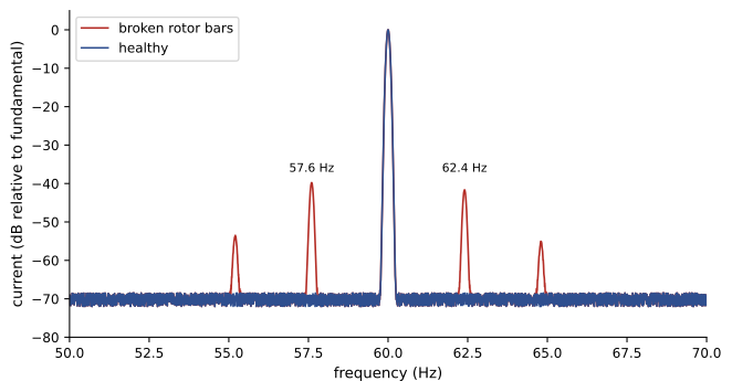
- Motor current signature analysis (MCSA): the spectrum of the stator current reveals rotor faults. A broken rotor bar produces an asymmetric rotor field that modulates the current, creating sidebands at \((1 \pm 2s)f\) around the supply frequency; their level relative to the fundamental indicates severity (sidebands more than about 50 dB below the fundamental are healthy, within 35 dB suggests broken bars). Eccentricity, bearing faults and load problems also leave signatures.
- Infrared thermography of terminal boxes, connections, bearings and frames.
- Lubricant and grease analysis for bearings and gearboxes.
- Online monitoring of winding temperature (RTDs or thermistors embedded in the windings), bearing temperature and, on large machines, PD and air-gap flux.
import numpy as np

# Condition monitoring frequencies for a 4-pole, 60 Hz induction motor at full load
f, poles = 60.0, 4
ns = 120 * f / poles
n = 1764.0                                         # measured speed, rpm
s = (ns - n) / ns
print(f"slip {s:.3f} ({ns - n:.0f} rpm)")
# Broken rotor bars: sidebands in the stator current spectrum at (1 +/- 2ks) f
for k in (1, 2):
    print(f"broken bar sidebands k={k}: {(1 - 2 * k * s) * f:.2f} Hz and {(1 + 2 * k * s) * f:.2f} Hz")
# Rolling bearing defect frequencies (6309 bearing: 8 balls, ball diameter 17.46 mm, pitch diameter 72.5 mm, contact angle 0)
nb, d, D = 8, 17.46, 72.5
fr = n / 60
ratio = d / D
bpfo = nb / 2 * fr * (1 - ratio)
bpfi = nb / 2 * fr * (1 + ratio)
bsf = D / (2 * d) * fr * (1 - ratio ** 2)
ftf = fr / 2 * (1 - ratio)
print(f"shaft {fr:.2f} Hz: outer race {bpfo:.1f} Hz, inner race {bpfi:.1f} Hz, ball spin {bsf:.1f} Hz, cage {ftf:.2f} Hz")
# Insulation resistance: polarization index from 1-minute and 10-minute readings
for r1, r10 in ((850, 2900), (400, 700), (60, 66)):
    pi_ = r10 / r1
    verdict = "good" if pi_ >= 2 else ("questionable" if pi_ >= 1.5 else "poor: moisture or contamination likely")
print(f"IR 1 min {r1} Mohm, 10 min {r10} Mohm: PI = {pi_:.2f} ({verdict})")slip 0.020 (36 rpm) broken bar sidebands k=1: 57.60 Hz and 62.40 Hz broken bar sidebands k=2: 55.20 Hz and 64.80 Hz shaft 29.40 Hz: outer race 89.3 Hz, inner race 145.9 Hz, ball spin 57.5 Hz, cage 11.16 Hz IR 1 min 850 Mohm, 10 min 2900 Mohm: PI = 3.41 (good) IR 1 min 400 Mohm, 10 min 700 Mohm: PI = 1.75 (questionable) IR 1 min 60 Mohm, 10 min 66 Mohm: PI = 1.10 (poor: moisture or contamination likely)
The sidebands of a broken bar lie only 2.4 Hz either side of 60 Hz at this load, so the analyzer needs high frequency resolution and the motor must be loaded: at no load the slip, and so the sideband spacing, is too small to see. Bearing defect frequencies are not integer multiples of running speed, which distinguishes them from unbalance and misalignment. The polarization index separates a clean winding from one that should be dried and cleaned before it is energized.
Bearings, alignment and drives
Because bearings cause the largest share of failures, their care matters most. Over-greasing is as harmful as under-greasing: excess grease churns and overheats, so regreasing follows the manufacturer's quantity and interval, with the drain plug open. Shaft misalignment between motor and load, even of a few tenths of a millimeter, overloads bearings and couplings; laser alignment to tolerances in the order of 0.05 mm for high-speed machines is standard practice. Soft foot, where one motor foot does not sit flat, distorts the frame. On variable-frequency drives, common-mode voltage induces shaft voltages that discharge through bearings, pitting the races in a pattern called fluting; shaft grounding rings, insulated or ceramic bearings, and drive output filters prevent it. Fast-rising PWM voltage pulses also stress turn-to-turn insulation, especially with long cables where reflected waves can nearly double the voltage at the motor terminals, so inverter-duty motors meeting NEMA MG 1 Part 31 or IEC 60034-18-41 should be used with drives, and dv/dt or sine filters fitted where cables are long.
Motor protection
Motor protection aims to disconnect the motor before damage occurs while allowing normal starting and permitted overloads. It has several layers:
- Short-circuit and ground-fault protection by fuses or circuit breakers in the branch circuit, sized to allow starting current while protecting the conductors.
- Overload protection with inverse-time characteristics matched to the motor's thermal capability. Overload relays are classified by trip class: Class 10 trips within 10 s at 6 times full-load current, suitable for most motors and required for many submersible pumps and hermetic compressors; Class 20 is the general-purpose default; Class 30 suits high-inertia loads with long starts.
- Electronic motor protection relays for larger motors, which model winding temperature from current (including negative-sequence heating from unbalance), detect phase loss, locked rotor and stall, underload (for example a pump running dry), ground fault, and read embedded RTDs.
- Undervoltage protection, to prevent motors reaccelerating together after a supply interruption and causing a large inrush, and to prevent overheating at low voltage.
In the US, motor circuits are governed by NEC Article 430 (Lesson 7 summarized its main rules): overload devices are generally set at not more than 125% of nameplate full-load current for motors with a service factor of 1.15 or more or a marked temperature rise of 40 °C or less, and 115% for others (430.32), with higher settings allowed where the motor will not start (430.32(C)). Motors in hazardous locations must be listed for the location class under Articles 500 to 506, and the authority having jurisdiction enforces installation requirements.
Large medium-voltage motors (above about 1,000 kW) add differential protection, as for transformers and generators (Lessons 4 and 10).
Maintenance strategy and repair
Maintenance strategies range from run-to-failure, acceptable for cheap, non-critical motors with spares on the shelf, through preventive maintenance at fixed intervals, to predictive and reliability-centered maintenance that matches effort to each machine's criticality and failure modes. A plant typically ranks its motors by the consequences of failure (safety, production loss, repair time) and applies online monitoring to the few critical machines, periodic route-based vibration and thermography to the important ones, and run-to-failure to the rest.
When a motor fails, the choice is between repair (rewinding) and replacement. Rewinding can reduce efficiency if the core is overheated during stripping or the winding is changed, so it should follow good practice standards such as ANSI/EASA AR100, which with proper procedures maintains efficiency. Replacement with a premium-efficiency motor is often more economical for motors below about 75 kW, considering the energy savings over the new motor's life (Lesson 7).
Bringing it together: specifying a motor and drive
A complete motor specification draws on every lesson in this course. Consider a cooling water pump for a data center, needing 55 kW at 1,780 rpm at the design flow, running continuously, with flow varying from 50 to 100% as cooling load changes.
| Decision | Choice and reasoning | Lesson |
|---|---|---|
| Machine type | three-phase induction (IE3 or IE4) or a SynRM/PMSM package for higher efficiency | 7, 11 |
| Rating | 75 kW frame: margin for pump curve uncertainty and drive derating; check the RMS load over the duty cycle | 8, 12 |
| Poles and speed | 4-pole (1,800 rpm synchronous) to match the pump speed directly | 6 |
| Speed control | VFD with V/f or sensorless vector control; affinity laws give large savings at part flow | 7, 8 |
| Motor construction | inverter-duty, Class F insulation with Class B rise, insulated non-drive-end bearing or shaft grounding ring | 12 |
| Supply effects | check harmonics at the point of common coupling; consider a low-harmonic drive | 4 |
| Protection | drive electronic overload and phase-loss protection, upstream short-circuit protection to code, winding thermistors | 12 |
| Monitoring | vibration sensors and bearing temperature for a critical pump; trend drive current | 12 |
Worked problem
Life-cycle energy of the pump motor
The pump needs 55 kW at full flow. Over a year it runs 30% of the time at 100% flow, 50% at 75% flow and 20% at 50% flow. Compare annual energy with a VFD (motor and drive efficiency 93%) and with throttling at constant speed (assume input power falls only to 90%, 80% of full-flow power at the lower flows, at 95% motor efficiency). Electricity costs $0.09/kWh.
Show solution
- VFD shaft power: 55, \(55 \times 0.75^3 = 23.2\) and \(55 \times 0.5^3 = 6.9\) kW. Input: 59.1, 24.9 and 7.4 kW.
- VFD energy: \(8{,}760 \times (0.3 \times 59.1 + 0.5 \times 24.9 + 0.2 \times 7.4) = 8{,}760 \times 31.7 = 277{,}700\) kWh.
- Throttled input: \(55/0.95 = 57.9\) kW at full flow, 52.1 kW and 46.3 kW at the lower flows; energy \(= 8{,}760 \times (17.4 + 26.1 + 9.3) = 8{,}760 \times 52.7 = 461{,}500\) kWh.
- Saving: \(183{,}800\) kWh, worth about $16,500 a year.
Answer: The VFD saves about 184 MWh and $16,500 a year, paying for the drive in one to two years. Over a 20-year life the electricity cost, around half a million dollars even with the drive, dwarfs the purchase price of the motor, which is why efficient machines and speed control dominate modern motor system design.
Common mistakes
MistakeIgnoring ambient temperature and altitude when sizing a motor.
InsteadApply derating factors; every 10 K hotter halves insulation life.
MistakeEnergizing a damp winding after a long shutdown.
InsteadMeasure IR and PI first; dry the winding if they are low.
MistakeOver-greasing bearings on a fixed schedule.
InsteadFollow the specified quantity and interval, with the drain open.
MistakeRunning a standard motor on a VFD with long cables.
InsteadUse inverter-duty motors, filters and bearing current mitigation.
MistakeSetting overload protection above the code limit to stop nuisance trips.
InsteadFind the cause (voltage, unbalance, overload, wrong trip class) and fix it.
Summary and key terms
- Insulation class and temperature rise set machine ratings; insulation life halves about every 10 K.
- Factory tests determine losses, efficiency, temperature rise and insulation strength to IEEE, CSA and IEC standards.
- IR, PI, surge and partial discharge tests track insulation condition in the field.
- Vibration analysis, current signature analysis and thermography detect faults early; broken bars show sidebands at \((1 \pm 2s)f\).
- Bearing care, alignment and VFD bearing-current mitigation address the leading cause of failures.
- Protection layers combine short-circuit, inverse-time overload, electronic relays and code requirements.
- Specifying a motor system integrates machine type, rating, speed control, construction, protection and monitoring.
- Thermal class
- The temperature rating of an insulation system.
- Temperature rise
- Winding temperature above ambient at rated load.
- Service factor
- A multiplier giving permissible continuous overload.
- Polarization index
- Ratio of 10-minute to 1-minute insulation resistance.
- Surge test
- A pulse test comparing phases to find weak turn insulation.
- Partial discharge
- Small electrical discharges in insulation voids.
- Motor current signature analysis
- Diagnosis of faults from the stator current spectrum.
- Bearing fluting
- Pitting of bearing races by shaft-voltage discharges.
- Trip class
- The maximum trip time of an overload relay at 6 times full-load current.
- Predictive maintenance
- Maintenance scheduled from measured condition.
Practice problems
Work each problem on paper first, then reveal the answer to check.
Maximum temperature of Class F insulation?
Show answer
155 °C.
Relative life of insulation running 20 K below its limit?
Show answer
About 4 times.
Combined derating for factors 0.95 and 0.9?
Show answer
0.855.
PI for readings of 300 MΩ at 1 min and 900 MΩ at 10 min?
Show answer
3.0, good.
Broken bar sidebands for s = 0.03 at 60 Hz?
Show answer
56.4 and 63.6 Hz.
At what frequency does an electrical problem show in vibration of a 60 Hz motor?
Show answer
120 Hz.
What does a Class 20 overload relay mean?
Show answer
It trips within 20 s at 6 times full-load current.
Name two causes of bearing failure in VFD-fed motors.
Show answer
Shaft voltage discharges (fluting), poor lubrication, misalignment.
Why must MCSA be done under load?
Show answer
Slip, and so sideband spacing, is too small at no load.
Shaft power of a 55 kW pump at 60% flow by the affinity laws?
Show answer
\(55 \times 0.6^3 = 11.9\) kW.
Lesson quiz · 5 questions
Score 60% or more to complete this lesson.
Create a free account to save your progress, take quizzes and earn a certificate.