
ELE-351 · Lesson 5 of 12 · 22 min
Frequency response and the DTFT
A filter specification is almost always written in the frequency domain: pass these frequencies, reject those, keep the delay constant across the band. To meet a specification, an engineer has to move fluently between a filter's coefficients and its frequency response. The tool for that is the discrete-time Fourier transform (DTFT), which is the z-transform evaluated on the unit circle. This lesson develops the DTFT and its properties, shows how to read magnitude and phase responses, distinguishes phase delay from group delay, explains why linear phase is valuable and when it is not needed, and introduces two special classes of filter, all-pass and minimum-phase, that appear whenever phase matters. The APS-2 example is an equalizer that corrects the response of the weatherproof speaker.
The discrete-time Fourier transform
The DTFT expresses a sequence as a continuous sum of complex exponentials e^(jωn). It is a function of the continuous frequency variable ω and is always periodic with period 2π, because e^(j(ω + 2π)n) = e^(jωn). The inverse transform integrates over any one period. Setting z = e^(jω) in the z-transform gives the DTFT, so the DTFT exists whenever the ROC includes the unit circle, which for a causal system means stability. The frequency response of an LTI system is the DTFT of its impulse response.
Its value is easiest to see with a sinusoid. If x[n] = e^(jω₀n) enters an LTI system, the output is H(e^(jω₀))e^(jω₀n): the same exponential, scaled by a complex number. A real cosine of amplitude A therefore comes out as A|H(e^(jω₀))| cos(ω₀n + ∠H(e^(jω₀))). The magnitude response says how much each frequency is amplified, and the phase response says how much it is shifted. Plotting both from 0 to π covers everything for a real filter, because for real h[n] the magnitude is even and the phase is odd in ω.
| Property | Sequence | DTFT |
|---|---|---|
| Linearity | ax[n] + by[n] | aX + bY |
| Time shift | x[n − n₀] | e^(−jωn₀)X(e^(jω)) |
| Modulation | e^(jω₀n)x[n] | X(e^(j(ω − ω₀))) |
| Convolution | x[n] * h[n] | X(e^(jω))H(e^(jω)) |
| Multiplication | x[n]w[n] | (1/2π) periodic convolution of X and W |
| Real sequence | x[n] real | X(e^(−jω)) = X*(e^(jω)) |
| Parseval | Σ|x[n]|² | (1/2π)∫|X(e^(jω))|² dω |
Reading magnitude and phase
Magnitude is usually plotted in decibels, 20 log₁₀|H|, against frequency in hertz or as a fraction of the Nyquist frequency. A designer reads the pass-band ripple, the stop-band attenuation and the width of the transition band from that plot. Phase is plotted in radians or degrees and is often wrapped into −π to π, which makes it look jagged. Unwrapping, adding multiples of 2π to remove the jumps, gives a smoother curve. Jumps of exactly π that remain after unwrapping are real: they happen wherever the magnitude passes through zero and the response changes sign.
Worked problem
The three-tap smoother
Find the frequency response of h[n] = 0.25, 0.5, 0.25 from lesson 1. Give its magnitude at DC, at f_s/4 and at f_s/2, and its phase.
Show solution
- \[H(e^{j\omega}) = 0.25 + 0.5e^{-j\omega} + 0.25e^{-j2\omega} = e^{-j\omega}\big(0.5 + 0.5\cos\omega\big)\]
- \[|H| = 0.5(1 + \cos\omega) = \cos^2(\omega/2)\]
- \[|H(e^{j0})| = 1, \quad |H(e^{j\pi/2})| = 0.5 \;(-6.0\ \text{dB}), \quad |H(e^{j\pi})| = 0\]
- \[\angle H = -\omega \;\Rightarrow\; \text{a constant delay of 1 sample}\]
Answer: The smoother is a gentle low-pass filter with a zero at the Nyquist frequency. Its phase is exactly −ω, a straight line, because the coefficients are symmetric about the middle tap. Every frequency is delayed by exactly one sample, so the shape of a waveform inside the pass band is preserved.
Phase delay and group delay
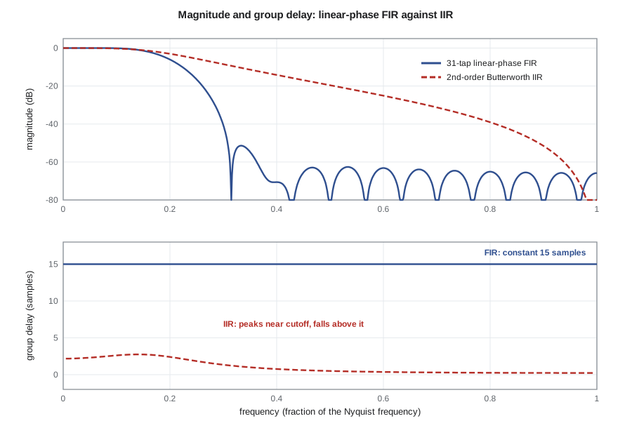
Two measures of delay come from the phase response. The phase delay τ_p(ω) = −∠H(e^(jω))/ω is the delay experienced by a single steady sinusoid. The group delay τ_g(ω) = −d∠H/dω is the delay of the envelope of a narrow-band signal centered at ω, such as a tone burst or a modulated carrier. When the phase is linear, both are constant and equal. When it is not, different frequencies are delayed by different amounts, which smears transients and changes waveform shapes, an effect called phase distortion.
A first-order IIR low-pass filter H(z) = (1 − a)/(1 − az⁻¹) shows the contrast. Its group delay is not constant: it is largest at DC, where it equals a/(1 − a) samples, and falls toward the Nyquist frequency. With a = 0.9 the low-frequency delay is 9 samples, while near f_s/2 it is about −0.47 samples, slightly negative. That variation is the price of the IIR filter's economy: one multiply gives a smoother that would take many taps as an FIR filter, but it does not delay all frequencies equally.
When linear phase matters
Linear phase is easy to get with FIR filters, as lesson 8 shows: any filter whose coefficients are symmetric or antisymmetric about the middle has exactly linear phase, with group delay (N − 1)/2 samples for N taps. Whether it is worth paying for depends on the application. Data receivers care a great deal, because phase distortion causes intersymbol interference; the raised-cosine filters of ELE-350 lesson 6 are linear-phase FIR filters for that reason. Measurement systems that compare waveforms, such as the echo canceller of lesson 12 or a system that measures the timing of events, need predictable delay. The ear, on the other hand, is quite tolerant of phase distortion in steady sounds, and the level meter of the APS-2 measures power, which phase does not change at all. For the A-weighting and high-pass filters, Amara therefore uses IIR filters and accepts their phase response.
All-pass filters
An all-pass filter has a magnitude response of exactly 1 at every frequency; it changes only phase. Each pole at p is paired with a zero at the reciprocal conjugate 1/p*, outside the circle, so the magnitudes of pole and zero vectors cancel everywhere on the unit circle. A first-order real all-pass has the form below. All-pass filters are used as phase equalizers, to flatten the group delay of an IIR filter where that matters, as building blocks of efficient filters and fractional delays, and in audio effects. They also explain why a filter's phase is not fixed by its magnitude: multiplying any filter by an all-pass changes its phase but not its magnitude.
Minimum phase
Many different filters share the same magnitude response. Among all causal, stable filters with a given magnitude, the one with all its zeros inside the unit circle is called minimum phase. It has the least phase lag and the least group delay at every frequency, and its energy is packed as early as possible in its impulse response. Any rational filter can be written as a minimum-phase filter times an all-pass filter, by reflecting zeros outside the circle to their reciprocal positions inside. Minimum-phase filters are important in two places in the APS-2. Their inverses are also causal and stable, because inverting turns zeros into poles, so a minimum-phase speaker model can be equalized exactly. And they give the lowest latency for a given magnitude response, which is why the output path uses minimum-phase IIR filters rather than linear-phase FIR filters wherever the waveform shape does not matter.
Equalizing the APS-2 speaker
Leo measures the weatherproof speaker in its pole housing and finds a broad dip of about 6 dB centered near 2.5 kHz, caused by the grille and the cavity behind it. Speech intelligibility depends heavily on the 1 to 4 kHz region, so Amara adds a peaking equalizer to the output path: a biquad that boosts a band around 2.5 kHz by 6 dB with a quality factor of 1.4 and leaves other frequencies alone. She computes the coefficients with the standard design equations for audio peaking filters, which place a pair of poles and a pair of zeros at the same angle, with the poles slightly closer to the circle than the zeros for a boost.
import cmath, math
fs = 48000
def peaking(f0, gain_db, Q):
    A = 10 ** (gain_db / 40); w0 = 2 * math.pi * f0 / fs; al = math.sin(w0) / (2 * Q)
    b = [1 + al * A, -2 * math.cos(w0), 1 - al * A]; a = [1 + al / A, -2 * math.cos(w0), 1 - al / A]
    return [v / a[0] for v in b], [v / a[0] for v in a]
def H(b, a, f):
    z1 = cmath.exp(-2j * math.pi * f / fs)
    return sum(bk * z1 ** k for k, bk in enumerate(b)) / sum(ak * z1 ** k for k, ak in enumerate(a))
def gd(b, a, f, df=0.5):                 # group delay in samples by differentiating the phase
    w = lambda ff: cmath.phase(H(b, a, ff))
    dphi = w(f + df) - w(f - df)
    dphi = (dphi + math.pi) % (2 * math.pi) - math.pi
    return -dphi / (2 * math.pi * 2 * df / fs)
b, a = peaking(2500, 6.0, 1.4)
print("b =", [round(v, 6) for v in b]); print("a =", [round(v, 6) for v in a])
for f in (100, 1000, 1800, 2500, 3500, 6000, 15000):
    h = H(b, a, f)
    print(f"{f:6d} Hz: {20*math.log10(abs(h)):6.2f} dB, phase {round(math.degrees(cmath.phase(h)), 2) + 0.0:7.2f} deg, group delay {gd(b, a, f):6.2f} samples")
r = abs(cmath.sqrt(a[2])); rz = abs(cmath.sqrt(b[2] / b[0]))
print(f"pole radius {r:.5f}, zero radius {rz:.5f}  (both inside: minimum phase)")
for name, aa in (("first-order low-pass a=0.9", 0.9),):
    for f in (0.001, 0.25 * fs / 2, 0.999 * fs / 2):
print(f"{name}: group delay at {f/(fs/2):5.3f} x Nyquist = {gd([1 - aa], [1, -aa], f, 0.01):6.2f} samples")b = [1.074807, -1.751511, 0.774866] a = [1.0, -1.751511, 0.849673] 100 Hz: 0.01 dB, phase 1.14 deg, group delay -1.53 samples 1000 Hz: 0.65 dB, phase 12.03 deg, group delay -1.71 samples 1800 Hz: 3.15 dB, phase 19.38 deg, group delay 0.22 samples 2500 Hz: 6.00 dB, phase 0.00 deg, group delay 6.14 samples 3500 Hz: 3.04 dB, phase -19.41 deg, group delay 0.03 samples 6000 Hz: 0.65 dB, phase -12.08 deg, group delay -0.32 samples 15000 Hz: 0.04 dB, phase -3.20 deg, group delay -0.06 samples pole radius 0.92178, zero radius 0.84908 (both inside: minimum phase) first-order low-pass a=0.9: group delay at 0.000 x Nyquist = 9.00 samples first-order low-pass a=0.9: group delay at 0.250 x Nyquist = -0.32 samples first-order low-pass a=0.9: group delay at 0.999 x Nyquist = -0.47 samples
The equalizer gives exactly +6.0 dB at 2.5 kHz and returns to within a fraction of a decibel of 0 dB below 500 Hz and above about 8 kHz. Its group delay peaks at about 6 samples, 0.13 ms, at the center frequency and is slightly negative on either side, which nobody will hear. Both the poles and the zeros are inside the unit circle, so the equalizer is minimum phase, and its inverse, a 6 dB cut, would also be a stable biquad. The first-order low-pass check confirms the 9-sample group delay at DC and the small negative value near the Nyquist frequency.
Ideal filters and why they cannot be built
The ideal low-pass filter passes everything below a cutoff ω_c with unity gain and zero phase and rejects everything above. Its impulse response, found from the inverse DTFT, is a sampled sinc that extends forever in both directions. It is therefore non-causal and not absolutely summable, so it is neither realizable nor strictly stable. Every practical filter is an approximation. A filter specification states how good the approximation must be: a pass band edge ω_p with ripple δ_p, a stop band edge ω_s with attenuation δ_s, and between them a transition band where the response is allowed to do anything. Lessons 8 and 9 design FIR and IIR filters to such specifications. The narrower the transition band and the smaller the ripples, the longer or higher-order the filter.
Common mistakes
MistakeCalling a wrapped phase plot with jumps evidence of instability.
InsteadWrapping to −π to π creates jumps of 2π; jumps of π occur at zeros of the magnitude. Neither indicates instability.
MistakeUsing phase delay to predict how a tone burst is delayed.
InsteadThe envelope of a narrow-band signal travels with the group delay, −dφ/dω.
MistakeInsisting on linear phase for every filter.
InsteadLinear phase matters for waveform fidelity and timing; for power measurement and most steady audio, minimum-phase IIR filters are cheaper and have less latency.
MistakeAssuming the magnitude response fixes the phase.
InsteadAny all-pass factor changes phase without changing magnitude; only the minimum-phase version is unique.
Summary and key terms
- The DTFT is the z-transform on the unit circle; it is 2π-periodic and exists for stable systems.
- An LTI system scales and shifts each sinusoid by |H(e^(jω))| and ∠H(e^(jω)).
- Group delay −dφ/dω describes envelope delay; constant group delay means linear phase and no phase distortion.
- Symmetric FIR filters have exact linear phase; IIR filters have frequency-dependent group delay.
- All-pass filters change only phase; minimum-phase filters have all zeros inside the circle, minimum delay and stable causal inverses.
- Ideal filters are non-causal; real designs approximate them within stated ripples and transition widths.
- DTFT
- The discrete-time Fourier transform, a continuous 2π-periodic function of frequency.
- Frequency response
- The DTFT of an impulse response, giving the gain and phase shift at each frequency.
- Phase delay
- The delay −φ(ω)/ω of a steady sinusoid through a system.
- Group delay
- The delay −dφ/dω of the envelope of a narrow-band signal.
- Linear phase
- A phase response proportional to frequency, giving constant delay.
- All-pass filter
- A filter with unit magnitude at all frequencies that changes only phase.
- Minimum phase
- A causal stable filter with all zeros inside the unit circle.
- Transition band
- The frequency range between pass band and stop band edges where the response is unconstrained.
Practice problems
Work each problem on paper first, then reveal the answer to check.
Find |H| at ω = π/3 for h[n] = 1, 1 (n = 0, 1).
Show answer
|1 + e^(−jπ/3)| = 2cos(π/6) = 1.732.
What is the group delay of a 41-tap symmetric FIR filter?
Show answer
(41 − 1)/2 = 20 samples.
Find the DC group delay of (1 − a)/(1 − az⁻¹) with a = 0.98.
Show answer
a/(1 − a) = 49 samples.
A filter has zeros at 2 and 0.5. Give a minimum-phase filter with the same magnitude response shape.
Show answer
Reflect the zero at 2 to 0.5: zeros at 0.5 and 0.5, with a gain of 2 to keep the magnitude equal.
Show that (0.5 − z⁻¹)/(1 − 0.5z⁻¹) has unit magnitude at ω = 0 and ω = π.
Show answer
At z = 1: (−0.5)/(0.5) = −1; at z = −1: (1.5)/(1.5) = 1.
A tone of 1 kHz passes through a filter with phase −1.2 rad at 1 kHz, sampled at 16 kHz. What is the phase delay?
Show answer
ω = 0.3927; τ_p = 1.2/0.3927 = 3.06 samples = 0.19 ms.
Lesson quiz · 5 questions
Score 60% or more to complete this lesson.
Create a free account to save your progress, take quizzes and earn a certificate.