
ELE-351 · Lesson 3 of 12 · 24 min
Quantization and data converters
Sampling makes time discrete; quantization makes amplitude discrete. A converter with N bits can represent only 2ᴺ levels, so every sample is rounded to the nearest one and the rounding error is lost for good. ELE-350 introduced the uniform quantizer and its rule of thumb, 6.02N + 1.76 dB for a full-scale sine. This lesson goes further, into the questions an engineer meets when choosing and using real converters: when the noise model is valid and what happens when it is not, why adding noise on purpose can make a signal cleaner, how sigma-delta converters trade speed for resolution, how data-sheet numbers such as ENOB and dynamic range relate to each other, and how to set the gain in front of a converter so that the whole range of real signals fits.
The quantizer and its noise model
A uniform quantizer with step size Δ maps every input to the nearest multiple of Δ. For a converter whose full-scale range is from −V_FS to +V_FS with N bits, Δ = 2V_FS/2ᴺ. As long as the input does not clip, the error e = Q(x) − x lies between −Δ/2 and Δ/2. If the input is busy, meaning it moves across many steps between samples in a way unrelated to the sampling, the error behaves like white noise, uniformly distributed with variance Δ²/12 and spread evenly from 0 to f_s/2. That is the additive noise model, and it leads directly to the familiar SQNR for a full-scale sine.
Real signals are rarely full-scale sines. A useful generalization uses the crest factor, the ratio of peak to rms. If the converter's full scale is set so that the signal's peaks just fit, the SQNR is reduced by the crest factor in decibels relative to a sine's 3 dB. Speech and street noise have crest factors of 12 to 20 dB, so a converter delivers about 10 to 17 dB less SQNR on them than its sine-wave figure. Signal levels are commonly given in dBFS, decibels relative to full scale, where 0 dBFS is the largest sine that does not clip.
When the model fails
The additive noise model breaks down for small or simple signals. A sine wave of amplitude 1.5 Δ is quantized to a staircase of only a few levels, and the error is then a deterministic, periodic waveform locked to the signal. Its energy appears not as a smooth noise floor but as harmonics of the signal, distortion that the ear and a spectrum analyzer both pick out easily. A slowly changing input can even sit on one level for a long time and produce no output change at all. In the APS-2 this matters at night, when the street is quiet and the microphone signal may be only a few steps of a 16-bit word after the firmware's internal scaling. It also matters inside the filters of lesson 10, where rounding happens in every multiply.
Dither
The cure is counterintuitive: add a small random noise, called dither, before quantizing. Dither randomizes the error so that it becomes independent of the signal, turning harmonic distortion into a benign noise floor. With triangular probability density function (TPDF) dither, the sum of two independent uniform random values each spanning one step, the first and second moments of the total error are independent of the signal, and the noise floor rises by a known amount, 4.77 dB. Recording studios dither when they reduce 24-bit masters to 16 bits, and DSP firmware does the same when it truncates a long accumulator to a short output word. Dither also lets the average of many quantized samples represent levels finer than one step, which is how a measurement system can resolve a fraction of an LSB.
import math, random
random.seed(7)
fs, f0, N = 48000, 1000, 4800          # 100 cycles exactly
def tone_level(x, f):                  # amplitude of the component at f (single-bin DFT)
    re = sum(v * math.cos(2 * math.pi * f * n / fs) for n, v in enumerate(x))
    im = sum(v * math.sin(2 * math.pi * f * n / fs) for n, v in enumerate(x))
    return 2 * math.hypot(re, im) / len(x)
A = 1.5                                # amplitude in quantizer steps (delta = 1)
x = [A * math.sin(2 * math.pi * f0 * n / fs) for n in range(N)]
plain = [round(v) for v in x]
tpdf = [round(v + random.uniform(-0.5, 0.5) + random.uniform(-0.5, 0.5)) for v in x]
for name, q in (("no dither", plain), ("TPDF dither", tpdf)):
    e = [a - b for a, b in zip(q, x)]
    h = [tone_level(q, k * f0) for k in (1, 3, 5)]
    print(f"{name:12s} error rms {math.sqrt(sum(v*v for v in e)/N):.3f} step | "
          f"fundamental {h[0]:.3f}, 3rd harmonic {20*math.log10(h[1]/h[0]):6.1f} dBc, 5th {20*math.log10(h[2]/h[0]):6.1f} dBc")
print(f"theory: undithered noise {math.sqrt(1/12):.3f}, TPDF total {math.sqrt(1/4):.3f} step rms")no dither error rms 0.327 step | fundamental 1.290, 3rd harmonic -18.5 dBc, 5th -25.8 dBc TPDF dither error rms 0.500 step | fundamental 1.492, 3rd harmonic -47.3 dBc, 5th -41.7 dBc theory: undithered noise 0.289, TPDF total 0.500 step rms
Without dither, the 1.5-step sine comes out with a third harmonic only about 18.5 dB below the fundamental, a distortion of about 12 percent, and a fifth harmonic 26 dB down; the fundamental itself is also measured about 14 percent low. With TPDF dither, the harmonics sink into the noise, 40 dB or more down, and the fundamental is measured correctly, at the cost of a total error of 0.5 step rms instead of 0.33. The extra noise is broadband and harmless; the harmonics it removed were tonal and misleading. Lesson 6 explains how such spectra are measured.
Oversampling and noise shaping
The quantization noise of an oversampled converter spreads over 0 to f_s/2. If only the band 0 to f_B is wanted, a digital filter can remove the rest, and the in-band noise falls by the oversampling ratio OSR = f_s/(2f_B). Plain oversampling gains 3 dB, half a bit, per doubling of the rate. That is slow: gaining 8 bits would need an OSR of 65 536. Noise shaping does much better. A sigma-delta modulator places the quantizer inside a feedback loop with an integrator, so that the quantization error is high-pass filtered: the noise is pushed out of the signal band toward f_s/2, where the decimation filter removes it.
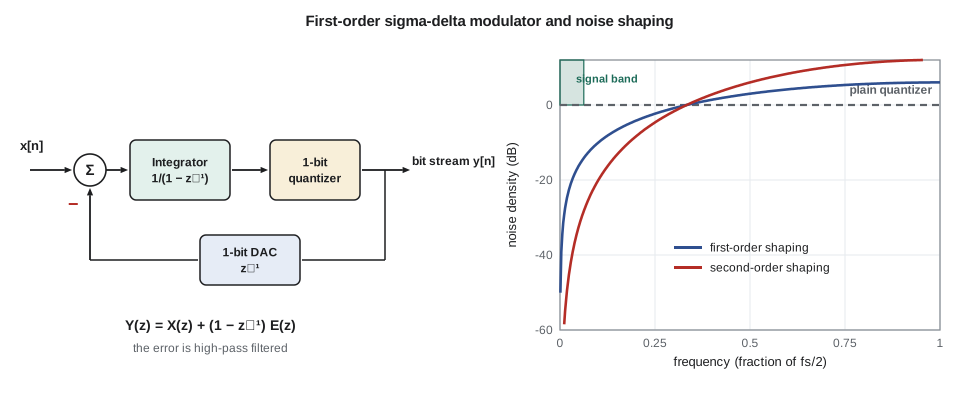
In a first-order modulator, the output in the z-domain of lesson 4 is Y(z) = X(z) + (1 − z⁻¹)E(z): the signal passes unchanged, and the error is filtered by a first difference, which has a zero at DC. Higher-order loops use (1 − z⁻¹)ᴸ and push the noise harder. The in-band noise power then falls by about 3(2L + 1) dB per doubling of the OSR: 9 dB per octave for a first-order loop and 15 dB per octave for second-order. A second-order modulator with a single-bit quantizer and an OSR of 64 reaches an ideal SQNR above 85 dB; practical audio codecs use third- to fifth-order loops and multibit quantizers to reach the 100 to 120 dB figures on their data sheets.
| Modulator order L | Gain per OSR doubling | Ideal SQNR, 1 bit, OSR 64 | Ideal SQNR, 1 bit, OSR 128 |
|---|---|---|---|
| 0 (plain oversampling) | 3 dB | 25.8 dB | 28.9 dB |
| 1 | 9 dB | 56.8 dB | 65.8 dB |
| 2 | 15 dB | 85.2 dB | 100.2 dB |
| 3 | 21 dB | 112.8 dB | 133.9 dB |
Converter specifications
Converter data sheets use several related measures, and it pays to know exactly what each one means. SNR is the ratio of a full-scale signal to the noise, excluding harmonics. Total harmonic distortion (THD) compares the harmonics to the fundamental. SINAD, or SNDR, compares the signal to everything else, noise plus distortion. The effective number of bits turns SINAD back into an equivalent ideal word length. Dynamic range is usually measured with a signal at −60 dBFS, so that distortion is negligible, and quoted as the ratio of full scale to the noise; audio specifications often apply A-weighting to it, which flatters the number by a few decibels. Static measures matter too: differential nonlinearity (DNL) is the deviation of each step from Δ, and integral nonlinearity (INL) is the deviation of the transfer curve from a straight line.
The codec Amara chose has 24-bit output words but a specified dynamic range of about 100 dB, which corresponds to an ENOB of roughly 16.3 bits. That is normal: the lower eight bits of each word mostly carry noise from the analog circuits. The extra word length is still useful, because it means the converter's own rounding never adds noise to the analog noise floor, and the firmware can apply gain digitally without exposing quantization steps.
Setting the gain
The most important converter decision in a product is often not the converter at all but the analog gain in front of it. Too much gain and loud signals clip; too little and quiet signals are buried in the converter's noise. The method is to list the largest signal that must pass without clipping and the smallest that must be measured, and then check that the span fits the converter's dynamic range with margin. For the APS-2 microphone, Amara works in sound pressure level, where 94 dB SPL is a pressure of 1 Pa rms.
Worked problem
Gain staging the APS-2 microphone
The microphone has a sensitivity of −42 dBV/Pa. The codec's full scale is 1.0 V rms (0 dBV) and its dynamic range is 100 dB. Amara wants a 110 dB SPL sine, louder than a bus passing at the curb, to just reach full scale. Find the analog gain needed, where 94 dB SPL sits in dBFS, and the equivalent sound level of the converter noise floor.
Show solution
- At 110 dB SPL the pressure is 16 dB above 1 Pa, so the microphone gives −42 + 16 = −26 dBV.
- \[G = 0\ \text{dBV} - (-26\ \text{dBV}) = 26\ \text{dB} \;(\text{a voltage gain of } 20)\]
- \[94\ \text{dB SPL} \to -42 + 26 = -16\ \text{dBV} = -16\ \text{dBFS}\]
- \[\text{noise floor} = 110 - 100 = 10\ \text{dB SPL equivalent}\]
Answer: A total gain of 26 dB, lower than the 40 dB of the revision B front end, puts 94 dB SPL at −16 dBFS and leaves 16 dB of headroom above it. The converter noise corresponds to only 10 dB SPL, far below the microphone's own self-noise, which for a small electret capsule is typically around 30 dB(A) SPL. The quietest night-time street, around 35 to 40 dB(A), is therefore still measurable, and the converter is not the limiting part.
import math
def sqnr_sd(N, L, osr):
    if L == 0:
        return 6.02 * N + 1.76 + 10 * math.log10(osr)
    return 6.02 * N + 1.76 - 10 * math.log10(math.pi ** (2 * L) / (2 * L + 1)) + (20 * L + 10) * math.log10(osr)
for L in range(4):
    print(f"order {L}: OSR 64 -> {sqnr_sd(1, L, 64):6.1f} dB, OSR 128 -> {sqnr_sd(1, L, 128):6.1f} dB")
for sinad in (98.0, 74.0, 62.0):
    print(f"SINAD {sinad:5.1f} dB -> ENOB {(sinad - 1.76) / 6.02:5.2f} bits")
sens, fs_dbv, dr = -42.0, 0.0, 100.0
for max_spl in (110, 120):
    gain = fs_dbv - (sens + (max_spl - 94))
    print(f"clip at {max_spl} dB SPL: gain {gain:4.1f} dB (x{10**(gain/20):5.1f}), 94 dB SPL at {sens + 0 + gain - fs_dbv:6.1f} dBFS, floor {max_spl - dr:5.1f} dB SPL")
for cf in (3.0, 12.0, 20.0):
print(f"16-bit word, crest factor {cf:4.1f} dB: SQNR {6.02*16 + 4.77 - cf:5.1f} dB")order 0: OSR 64 -> 25.8 dB, OSR 128 -> 28.9 dB order 1: OSR 64 -> 56.8 dB, OSR 128 -> 65.8 dB order 2: OSR 64 -> 85.2 dB, OSR 128 -> 100.2 dB order 3: OSR 64 -> 112.8 dB, OSR 128 -> 133.9 dB SINAD 98.0 dB -> ENOB 15.99 bits SINAD 74.0 dB -> ENOB 12.00 bits SINAD 62.0 dB -> ENOB 10.01 bits clip at 110 dB SPL: gain 26.0 dB (x 20.0), 94 dB SPL at -16.0 dBFS, floor 10.0 dB SPL clip at 120 dB SPL: gain 16.0 dB (x 6.3), 94 dB SPL at -26.0 dBFS, floor 20.0 dB SPL 16-bit word, crest factor 3.0 dB: SQNR 98.1 dB 16-bit word, crest factor 12.0 dB: SQNR 89.1 dB 16-bit word, crest factor 20.0 dB: SQNR 81.1 dB
The code reproduces the table and the gain calculation, and it shows how much the crest factor matters: a 16-bit word that gives 98 dB on a full-scale sine gives only about 81 dB on a signal with a 20 dB crest factor scaled so that its peaks just fit. Inside the firmware, Amara will therefore keep audio in 32-bit words with headroom, and reduce to 16 bits only where memory is tight, with dither.
Clipping and its consequences
When a signal exceeds full scale, the converter clips it to the largest code. Clipping is not gentle. It creates harmonics and intermodulation products spread across the whole band, and in a sampled system the high harmonics alias back into the band as inharmonic tones. In the APS-2, clipping of the microphone signal during a passing truck or a nearby horn would also make the level meter read too low, because clipped peaks carry less energy than the real ones. Amara adds a clip counter to the firmware: if more than a few samples per second reach full scale, the level estimate is flagged as unreliable and the volume control holds its last good value. The output side needs the same care. The volume control multiplies the signal by a gain, and the mixer adds voice and tone; either can push a sum past full scale. Saturating arithmetic, which clamps instead of wrapping around, is mandatory on the output path, a topic lesson 10 returns to.
Common mistakes
MistakeQuoting SQNR from 6.02N + 1.76 for a speech or noise signal.
InsteadSubtract the crest factor penalty; speech can lose 10 to 17 dB relative to a full-scale sine.
MistakeAssuming quantization error is always white noise.
InsteadFor small or periodic signals the error is correlated with the signal and appears as harmonics; dither restores the noise model.
MistakeReading a 24-bit codec as 144 dB of dynamic range.
InsteadUse the specified dynamic range or SINAD; ENOB is often 16 to 20 bits.
MistakeSetting front-end gain for the typical signal only.
InsteadSet it so the largest expected signal just fits, then check that the smallest is above the noise.
Summary and key terms
- A uniform quantizer adds error of variance Δ²/12 when the signal is busy; SQNR for a full-scale sine is 6.02N + 1.76 dB, less the crest factor penalty for real signals.
- For small or periodic signals the error becomes harmonic distortion; TPDF dither makes it signal-independent noise at a 4.77 dB noise cost.
- Oversampling alone gains 3 dB per doubling; sigma-delta noise shaping of order L gains about 3(2L + 1) dB per doubling.
- SNR, THD, SINAD, ENOB and dynamic range measure different things; ENOB = (SINAD − 1.76)/6.02.
- Gain staging places the largest expected signal at full scale and checks the noise floor against the smallest signal.
- Clipping creates wideband distortion and aliased tones; firmware should detect it and use saturating arithmetic.
- Quantization step
- The spacing Δ between adjacent levels of a uniform quantizer.
- dBFS
- Level in decibels relative to the largest sine wave that does not clip.
- Crest factor
- The ratio of a signal's peak value to its rms value.
- Dither
- Noise deliberately added before quantization to make the error independent of the signal.
- Noise shaping
- Filtering quantization error with a feedback loop so that its power moves out of the signal band.
- Sigma-delta modulator
- An oversampling converter with an integrator and a coarse quantizer in a feedback loop.
- ENOB
- Effective number of bits, the word length of an ideal converter with the same SINAD.
- Dynamic range
- The ratio of full-scale signal to the noise floor, usually measured with a small test signal.
Practice problems
Work each problem on paper first, then reveal the answer to check.
A 12-bit converter has a ±2.5 V range. Find Δ and the rms quantization noise.
Show answer
Δ = 5/4096 = 1.22 mV; rms noise = Δ/√12 = 0.35 mV.
A converter measures SINAD = 86 dB. What is its ENOB?
Show answer
(86 − 1.76)/6.02 = 14.0 bits.
How much does plain oversampling by 16 improve in-band SQNR?
Show answer
10 log₁₀ 16 = 12 dB, two bits.
How much does a second-order modulator gain when its OSR goes from 64 to 256?
Show answer
Two doublings at 15 dB each, about 30 dB.
A microphone gives −38 dBV/Pa and the converter clips at +6 dBV. What gain makes 120 dB SPL just clip?
Show answer
Mic output at 120 dB SPL = −38 + 26 = −12 dBV; gain = 6 − (−12) = 18 dB.
Why does TPDF dither raise the noise floor by about 4.77 dB?
Show answer
Total error variance becomes Δ²/4 instead of Δ²/12, a factor of 3, which is 4.77 dB.
Lesson quiz · 5 questions
Score 60% or more to complete this lesson.
Create a free account to save your progress, take quizzes and earn a certificate.