
ELE-351 · Lesson 11 of 12 · 20 min
Multirate signal processing
Real DSP systems rarely run everything at one sample rate. The APS-2 receives audio from its codec at 48 kHz, analyzes it at 16 kHz and plays voice prompts recorded at 16 kHz through a 48 kHz DAC. The codec itself converts between 48 kHz and a modulator rate of 3.072 MHz. A software radio digitizes at megahertz rates and decimates down to a few tens of kilohertz for each channel. Changing the sample rate correctly, without aliasing on the way down or images on the way up, and doing it cheaply, is the subject of multirate signal processing. This lesson covers downsampling and upsampling in the frequency domain, decimation and interpolation filters, the noble identities and polyphase structures that cut their cost, rational rate changes, multistage designs, and the multiplier-free CIC filters used at the highest rates.
Downsampling and aliasing
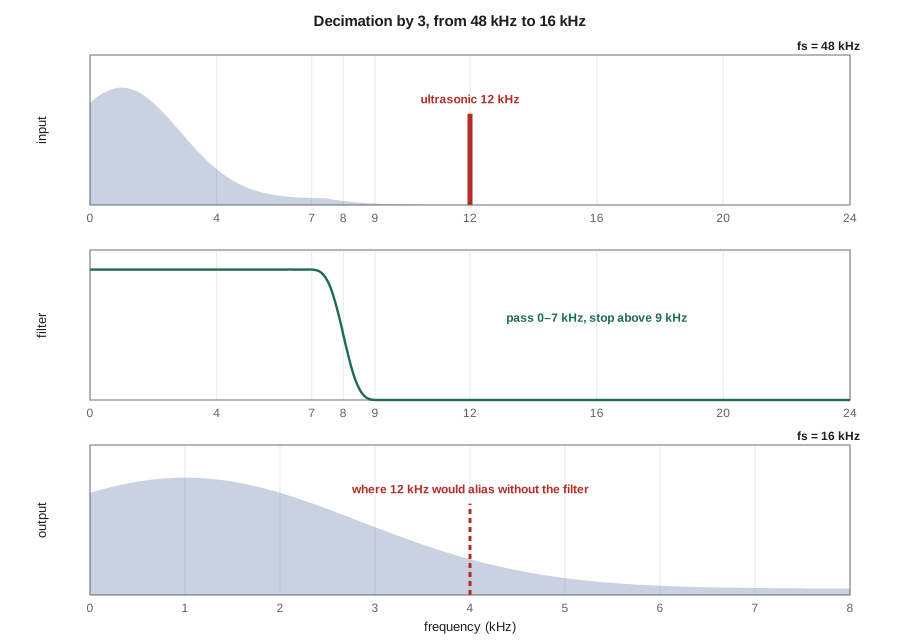
Downsampling by an integer M keeps every M-th sample and discards the rest: y[n] = x[Mn]. The new sample rate is f_s/M, and so is the new Nyquist frequency. In the frequency domain, the spectrum is stretched by M and overlapping copies are added, so everything between the new Nyquist frequency f_s/(2M) and the old one folds into the new band. Downsampling is therefore exactly like sampling an analog signal at a lower rate, and it needs exactly the same protection: a low-pass decimation filter applied before discarding samples.
For the APS-2 decimation from 48 to 16 kHz, the new Nyquist frequency is 8 kHz. A component at f between 8 and 24 kHz appears after decimation at its alias inside 0 to 8 kHz; a 12 kHz tone, for example, appears at 4 kHz. The level meter and spectrum monitor use 0 to 7 kHz, so the filter must remove everything that would fold into that range. Frequencies from 8 to 9 kHz fold into 7 to 8 kHz, which is not used, so the stop band can start at 9 kHz. That is exactly the specification of the interpolation filter designed in lesson 8: pass to 7 kHz, stop from 9 kHz at a 48 kHz rate, 70 dB. One design serves both directions.
Upsampling and images
Upsampling by an integer L inserts L − 1 zeros between samples. The new sample rate is Lf_s. The spectrum is compressed by L: the original spectrum, which repeated every f_s, now repeats every f_s within the new, wider band, so L − 1 images of the signal appear between 0 and the new Nyquist frequency. An interpolation filter, a low-pass filter at the new rate with cutoff at the old Nyquist frequency and a gain of L, removes the images and fills in the zeros with interpolated values. The gain of L restores the amplitude lost by inserting zeros.
The noble identities and polyphase filters
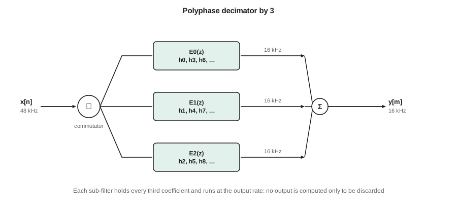
Done literally, decimation wastes effort: the filter computes every output at the high rate, and then M − 1 of every M are thrown away. Interpolation wastes effort too: the filter multiplies inserted zeros. Two identities, called the noble identities, let filters move across rate changers. A filter H(z^M) followed by downsampling by M equals downsampling followed by H(z); upsampling by L followed by H(z^L) equals H(z) followed by upsampling. Combined with the polyphase decomposition, which splits any FIR filter into M sub-filters made of every M-th coefficient, they turn the wasteful structures into efficient ones.
A polyphase decimator feeds each sub-filter E_k with every M-th input sample, offset by k, runs all the sub-filters at the low rate and adds their outputs. Every multiply produces a sample that is kept, so the cost falls by a factor of M. A polyphase interpolator runs the L sub-filters at the low input rate and takes their outputs in turn, a commutator, to form the high-rate output; no multiply ever touches an inserted zero, so the cost also falls by L. For the APS-2's 109-tap filter, the direct structures cost 109 multiplies per 48 kHz sample; the polyphase versions cost 109 per 16 kHz sample, a third as much, before even counting the zero coefficients that the M-th-band design of lesson 8 provides.
Rational rate changes
A rate change by a rational factor L/M is an interpolation by L followed by a decimation by M, with a single low-pass filter between them whose cutoff is the smaller of the two Nyquist frequencies. Implemented in polyphase form, the filter computes only the outputs that are kept. The classic example is between the 44.1 kHz rate of consumer audio and the 48 kHz rate of professional and broadcast audio, a ratio of 160/147. Voice prompts that a city records in its own studio often arrive at 44.1 or 48 kHz. Cedarline's configuration tool converts them on a laptop to 16 kHz before they are loaded into the APS-2, a factor of 160/441 from 44.1 kHz or 1/3 from 48 kHz, so the device itself only ever has to interpolate by 3. Where rates are not related by small integers, or drift slowly as with two independent crystal clocks, asynchronous sample-rate converters compute the output at arbitrary times by interpolating between polyphase branches.
Multistage design
When the rate change is large, doing it in one step needs a very long filter, because the transition band is narrow relative to the high input rate. Splitting the change into stages helps enormously. The early stages run at high rates but only need to protect the final band from aliasing, so their transition bands can be wide and their filters short. The last stage runs at a low rate, where a sharp filter is cheap. Decimating the codec's 3.072 MHz modulator output to 48 kHz, a factor of 64, in one stage would need a filter with a transition from 20 to 28 kHz at 3.072 MHz, thousands of taps. In practice converters use a cascade: a CIC filter that decimates by 8 or 16, then two or three half-band filters that each decimate by 2, and a final sharp FIR stage. The code below compares the costs.
CIC filters
At the highest rates, even short FIR filters need fast multipliers. The cascaded integrator-comb (CIC) filter, described by Hogenauer in 1981, needs none. It is K integrators y[n] = y[n − 1] + x[n] at the high rate, a downsampler by R, and K comb sections y[n] = x[n] − x[n − 1] at the low rate. Its transfer function is that of K cascaded moving averages of length R, and its frequency response is a sinc raised to the K-th power, with nulls at multiples of the output rate, which is exactly where aliases would otherwise land in the center of the output band. Its integrators overflow freely, but in two's-complement arithmetic with enough register bits, K log₂ R plus the input word length, the wrap-arounds cancel exactly in the combs.
The CIC's weakness is droop: its sinc response is not flat across the pass band, and its alias rejection near the band edge is limited. The stages after it fix both, with a compensation filter whose response rises gently to cancel the droop. The code computes the droop and rejection for a fourth-order CIC decimating by 16.
import math, cmath
def i0(x):
    s, t, k = 1.0, 1.0, 1
    while t > 1e-12 * s:
        t *= (x / (2 * k)) ** 2; s += t; k += 1
    return s
def kaiser(N, wc, beta):
    a = (N - 1) / 2
    return [(wc / math.pi if n == a else math.sin(wc * (n - a)) / (math.pi * (n - a))) * i0(beta * math.sqrt(1 - (2 * n / (N - 1) - 1) ** 2)) / i0(beta) for n in range(N)]
h = kaiser(109, math.pi / 3, 6.976)          # the lesson 8 design: pass 7 kHz, stop 9 kHz at 48 kHz
M = 3
x = [math.sin(2 * math.pi * 1000 * n / 48000) + 0.5 * math.sin(2 * math.pi * 12000 * n / 48000) for n in range(4800)]
full = [sum(h[k] * x[n - k] for k in range(len(h)) if n - k >= 0) for n in range(len(x))]
direct = full[::M]
phases = [h[k::M] for k in range(M)]          # polyphase decimator
poly = []
for m in range(len(x) // M):
    acc = 0.0
    for k, e in enumerate(phases):
        for j, c in enumerate(e):
            idx = m * M - k - j * M
            if idx >= 0: acc += c * x[idx]
    poly.append(acc)
print(f"polyphase vs filter-then-downsample: max difference {max(abs(p - q) for p, q in zip(poly, direct)):.1e}")
def level(sig, f, fs):
    sig = sig[len(sig) // 4:]; n = len(sig)
    return 2 * abs(sum(v * cmath.exp(-2j * math.pi * f * i / fs) for i, v in enumerate(sig))) / n
print(f"at 16 kHz: 1 kHz tone {level(poly, 1000, 16000):.4f}, alias of 12 kHz at 4 kHz {20*math.log10(level(poly, 4000, 16000)/0.5):.1f} dB rel. input")
nz = sum(1 for c in h if abs(c) > 1e-12)
print(f"multiplies per second: direct {len(h)*48000/1e6:.2f} M, polyphase {len(h)*16000/1e6:.2f} M, polyphase skipping zero taps {nz*16000/1e6:.2f} M")
# CIC: order 4, decimate by 16 from 3.072 MHz
K, R, fin = 4, 16, 3.072e6
def cic(f): return abs(math.sin(math.pi * f * R / fin) / (R * math.sin(math.pi * f / fin))) ** K if f else 1.0
fout = fin / R
print(f"CIC K={K}, R={R}: output {fout/1e3:.0f} kHz, droop at 20 kHz {20*math.log10(cic(20e3)):.2f} dB,"
      f" rejection at {fout/1e3 - 20:.0f} kHz {20*math.log10(cic(fout - 20e3)):.1f} dB, register bits for 4-bit input {4 + K*int(math.log2(R))}")
# single-stage versus multistage decimation by 64 (Harris estimate N = A/(22 df/fs))
A = 100
single = A / (22 * 8e3 / fin)
stages = [("half-band 192->96 kHz", 192e3, 96e3 - 20e3 - 20e3), ("half-band 96->48 kHz", 96e3, 48e3 - 20e3 - 20e3)]
cost_multi = 0.0
for name, fs, df in stages:
    taps = A / (22 * df / fs); cost_multi += taps / 4 * fs / 2
    print(f"{name}: about {taps:.0f} taps")
print(f"single stage at 3.072 MHz: about {single:.0f} taps, {single*fout/4/1e6:.0f} M multiplies/s (polyphase, symmetric)")
print(f"CIC (no multiplies) + half-bands: about {cost_multi/1e6:.1f} M multiplies/s")polyphase vs filter-then-downsample: max difference 1.0e-15 at 16 kHz: 1 kHz tone 1.0000, alias of 12 kHz at 4 kHz -88.9 dB rel. input multiplies per second: direct 5.23 M, polyphase 1.74 M, polyphase skipping zero taps 1.17 M CIC K=4, R=16: output 192 kHz, droop at 20 kHz -0.62 dB, rejection at 172 kHz -75.2 dB, register bits for 4-bit input 20 half-band 192->96 kHz: about 16 taps half-band 96->48 kHz: about 55 taps single stage at 3.072 MHz: about 1745 taps, 84 M multiplies/s (polyphase, symmetric) CIC (no multiplies) + half-bands: about 1.0 M multiplies/s
The polyphase decimator gives exactly the same output as filtering at 48 kHz and discarding two samples in three, at a third of the cost; skipping the zero coefficients saves another third. The 12 kHz component that would alias to 4 kHz is suppressed by more than 70 dB, as the filter was designed to do. The CIC figures show its character: a droop of a fraction of a decibel at 20 kHz, which the following filters must correct, and strong rejection near the first alias. The last comparison is the reason every audio converter is multistage. A single filter at 3.072 MHz would need nearly two thousand taps and over 80 million multiplies per second even in polyphase form; the CIC followed by two half-band stages needs about one million, and the CIC itself needs no multiplier at all.
Multirate in the TLR-1
The same ideas run the radio side. The TLR-1 receiver of ELE-350 produces a digitized intermediate frequency; in the direct-IF design considered in lesson 2, samples at 2.5 MHz contain the 200 kHz band folded to 0.6 to 0.8 MHz. A digital mixer multiplies by a complex exponential to shift the band to zero, and a decimation chain, a CIC by 10 followed by a compensating FIR filter decimating by 5, brings the rate down to 50 kHz, where the GFSK demodulator works on one channel. Changing channel means changing only the mixer frequency. That is the essence of a software-defined radio, and it is built entirely from the blocks of this lesson.
Common mistakes
MistakeDownsampling without a decimation filter.
InsteadEverything between the new and old Nyquist frequencies aliases into the band; filter first, or use a polyphase decimator.
MistakeForgetting the gain of L in an interpolation filter.
InsteadZero insertion reduces the average amplitude by L; the filter's pass-band gain must be L.
MistakeDesigning a large rate change as one stage.
InsteadSplit it; early stages with wide transitions are short, and the sharp filter runs at the low rate.
MistakeSizing CIC registers for the input word only.
InsteadIntegrators need B_in + K log₂ R bits so that wrap-around cancels in the combs.
Summary and key terms
- Downsampling by M stretches and overlaps the spectrum; a decimation filter must remove what would alias into the band used.
- Upsampling by L creates L − 1 images; an interpolation filter with gain L removes them.
- The noble identities and polyphase decomposition run each sub-filter at the low rate, cutting cost by M or L.
- Rational changes L/M combine interpolation and decimation with one shared filter.
- Multistage designs make large rate changes cheap by giving early stages wide transition bands.
- CIC filters decimate or interpolate without multipliers; their sinc^K response needs droop compensation.
- Downsampling
- Keeping every M-th sample of a sequence.
- Upsampling
- Inserting L − 1 zeros between samples of a sequence.
- Decimation
- Low-pass filtering followed by downsampling.
- Interpolation
- Upsampling followed by low-pass filtering to remove images.
- Noble identities
- Rules for moving a filter across a downsampler or upsampler by replacing z with z^M.
- Polyphase decomposition
- Splitting a filter into M sub-filters made of every M-th coefficient.
- Multistage design
- Performing a large rate change in several smaller steps.
- CIC filter
- A cascaded integrator-comb filter that changes sample rate without multiplications.
Practice problems
Work each problem on paper first, then reveal the answer to check.
A 48 kHz signal is decimated by 4. Where does an unfiltered 20 kHz component appear?
Show answer
New rate 12 kHz; 20 − 2 × 12 = −4, so at 4 kHz.
A signal at 8 kHz is upsampled by 6. At what frequencies do images of a 1 kHz tone appear below 24 kHz?
Show answer
7, 9, 15, 17 and 23 kHz.
How many sub-filters and taps each does a 96-tap filter have in a polyphase decimator by 4?
Show answer
4 sub-filters of 24 taps.
Give L/M to convert 48 kHz to 44.1 kHz.
Show answer
147/160.
What register width does a fifth-order CIC need with R = 32 and 16-bit input?
Show answer
16 + 5 × 5 = 41 bits.
Why can the first stage of a multistage decimator have a wide transition band?
Show answer
It need only stop frequencies that would alias into the final band after all stages; others are removed later.
Lesson quiz · 5 questions
Score 60% or more to complete this lesson.
Create a free account to save your progress, take quizzes and earn a certificate.