
ELE-351 · Lesson 10 of 12 · 25 min
Filter structures and finite word-length effects
A filter designed in double-precision arithmetic on a desktop computer must eventually run on a processor that stores coefficients and signals in a limited number of bits. Many algebraically identical arrangements of the same difference equation exist, and in finite precision they behave very differently: one structure may meet the specification while another, with exactly the same ideal response, misses it by tens of decibels, adds audible noise or oscillates on its own. This lesson covers the common structures for FIR and IIR filters, fixed-point number formats, the effects of coefficient quantization, roundoff noise, overflow and scaling, and the strange nonlinear behavior called limit cycles. CMP-450 studied these effects for an FIR filter in hardware; here the focus is on the IIR biquads of the APS-2 firmware, where the effects are much stronger.
Fixed-point formats
Most DSP firmware on small processors uses fixed-point fractions. A Qm.n number has m integer bits including the sign and n fractional bits; its value is the stored integer divided by 2ⁿ. Q1.15, a 16-bit word with 15 fractional bits, covers −1 to just under +1 with a step of about 3 × 10⁻⁵. Q1.31 does the same in 32 bits with a step of 4.7 × 10⁻¹⁰. Biquad feedback coefficients can approach 2 in magnitude, because a₁ = −2r cos θ, so they need at least two integer bits, as in Q2.14 or Q2.30. The product of two Q1.15 numbers is a Q2.30 number in a 32-bit result, and a MAC unit accumulates such products in a wider accumulator, often 40 or 64 bits, before the result is rounded back to the output format. Floating-point processors avoid most scaling decisions, but single-precision float still has only 24 bits of mantissa, which, as this lesson shows, is not enough for some IIR filters at high sample rates.
Structures for FIR filters
The direct form of an FIR filter is the tapped delay line: delay the input, multiply each delayed value by a coefficient and add the products. The transposed direct form moves the delays to the adder chain instead. Both compute exactly the same thing in infinite precision. In fixed point, the direct form with a wide accumulator rounds only once, at the end, which makes its noise easy to predict, and symmetric coefficients let pairs of inputs be added before multiplying. FIR filters have no feedback, so coefficient rounding changes the response only slightly and predictably, and rounding errors never recirculate. That is why CMP-450 could predict its FIR filter's SNR almost exactly from the word lengths.
Structures for IIR filters
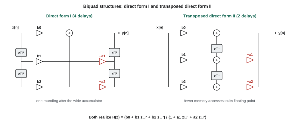
For IIR filters, four direct structures are common. Direct form I computes the feedforward part from stored past inputs and the feedback part from stored past outputs, using 2N delays for an N-th-order section. Direct form II, the canonical form, shares one delay line between the two parts, using only N delays, by applying the feedback first and the feedforward second. The transposed forms of each rearrange the delays and adders. All four have the same transfer function. In fixed point, direct form I with a wide accumulator is usually preferred: its only internal signals are the input and output, which are already scaled, and it rounds once per output. Direct form II is attractive in floating point, especially in its transposed version, because it needs fewer memory accesses and has good numerical properties there, but in fixed point its internal state can be much larger than the input or output, as the code below shows.
A high-order IIR filter should never be implemented as one direct-form difference equation. The roots of a high-order polynomial are extremely sensitive to small changes in its coefficients, so rounding the coefficients of, say, a sixth-order denominator can move poles far from their design positions or even outside the unit circle. Splitting the filter into second-order sections confines each coefficient's influence to one pole pair. The cascade form connects the biquads in series; the parallel form, from a partial-fraction expansion, adds their outputs. Cascade is far more common in audio. Lattice and wave digital structures have even lower sensitivity and guaranteed stability properties and appear in speech coding and some specialized filters, at the cost of more multiplies.
Coefficient quantization
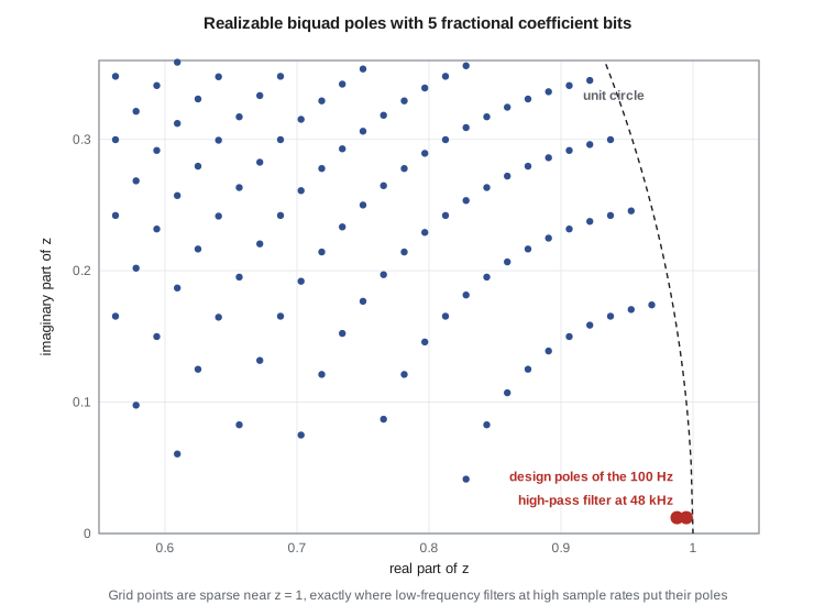
Rounding the coefficients of a biquad to a fixed number of bits restricts where its poles can be. With a₁ = −2r cos θ and a₂ = r², the realizable poles of a direct-form biquad form a grid in the z-plane that is dense near θ = π/2 and sparse near z = 1 and z = −1. A low-frequency filter at a high sample rate puts its poles exactly where the grid is sparsest. The 100 Hz high-pass filter at 48 kHz from lesson 9 has poles at angles of only about 0.013 rad, with radii above 0.98. Its feedback coefficients are close to −2 and +1, and the information that defines the filter lies in their last few digits. Rounded to Q2.14, with a step of 6.1 × 10⁻⁵, the poles move far enough to change the cutoff and the Q noticeably.
Worked problem
Pole movement from coefficient rounding
The higher-Q section of the high-pass filter has a₁ = −1.98986110 and a₂ = 0.99003159. Find its poles, then round the coefficients to Q2.14 and find how far the pole angle moves.
Show solution
- \[r = \sqrt{a_2} = 0.995003 \qquad \theta = \arccos\Big(\frac{-a_1}{2r}\Big) = \arccos(0.9999272) = 0.01209\ \text{rad} \;\to\; 92.4\ \text{Hz}\]
- \[a_1^{(Q2.14)} = \frac{\text{round}(-1.98986110 \times 16384)}{16384} = -1.98986816 \qquad a_2^{(Q2.14)} = 0.99005127\]
- \[r' = 0.995013, \quad \theta' = \arccos(0.9999204) = 0.01262\ \text{rad} \;\to\; 96.4\ \text{Hz}\]
Answer: Rounding to 14 fractional bits moves this pole pair from 92.4 Hz to about 96.4 Hz and changes its damping, an error of 4 percent in frequency from a coefficient change of less than one part in a hundred thousand. The code below shows the effect on the response and that Q2.30 coefficients remove the problem.
Three remedies exist. Use longer coefficients: 32-bit Q2.30 coefficients on a processor with a 32 × 32-bit multiply, as Amara chooses, make the error negligible. Run the low-frequency filter at a lower sample rate, after decimation, where its poles move away from z = 1; this is often the best answer, but the APS-2 needs the high-pass filter before decimation to protect the decimator's headroom. Or use a structure whose pole grid is dense near z = 1, such as the coupled form, in which the coefficients are r cos θ and r sin θ directly, or a delta-operator form that implements the filter in terms of differences of successive samples. Single-precision floating point, with 24 bits of mantissa, sits between the Q2.14 and Q2.30 cases; for this filter it is adequate, but for a 20 Hz filter at 96 kHz it would not be.
Roundoff noise
Every time a product or a sum is rounded to a shorter word, an error of variance Δ²/12 is added, as in lesson 3. In an FIR filter with a wide accumulator, there is one rounding per output, and the output noise is just Δ²/12. In an IIR filter, rounding errors inside the feedback loop are themselves filtered by the loop's transfer function 1/A(z) before they reach the output, and for a filter with poles close to the unit circle, that transfer function has a large gain at the pole frequency. The output noise variance is Δ²/12 times the noise gain, the sum of the squares of the impulse response from the rounding point to the output. For the APS-2 high-pass filter in direct form I with a 16-bit output word, the error is shaped by the poles near 100 Hz; with a 32-bit state and accumulator, it is buried far below the converter's noise.
Overflow and scaling
Fixed-point signals must not exceed the format's range. If a sum overflows in two's-complement arithmetic and wraps around, a large positive value becomes a large negative one, a disaster in audio and potentially a source of sustained oscillation in a recursive filter. Two defenses are combined. Saturating arithmetic clamps overflowing results to the largest representable value, turning catastrophic wrap-around into ordinary clipping; DSP instruction sets provide saturating adds for this reason. Scaling ensures that overflow is rare in the first place by choosing gains so that internal signals stay in range. The required scale depends on the norm used: the L1 norm, the sum of |h[n]| from input to the node, guarantees no overflow for any input; the L∞ norm of the frequency response, the peak gain, guarantees it for sinusoids; the L2 norm guarantees it on average for random signals. The L1 rule is safe but pessimistic; most audio designs scale by the peak gain with a few decibels of headroom and rely on saturation for the rest.
Direct form II shows why the structure matters for scaling. Its internal state w[n] is the input filtered by 1/A(z) alone, before the zeros act. For the high-pass biquads, 1/A(z) is a low-pass resonance near 100 Hz with an enormous gain at DC, because the zeros that cancel it are applied afterward. A small DC offset from the microphone receiver, harmless at the input and removed entirely at the output, can therefore overflow the state of a direct form II section. Direct form I has no such internal node, which is the main reason Amara uses it.
Limit cycles
Rounding inside a feedback loop makes the filter nonlinear, and nonlinear systems can do things LTI systems cannot. The best known is the zero-input limit cycle: after the input stops, the output of an ideal stable filter decays to zero, but the rounded filter may get stuck at a small nonzero value or oscillate between a few levels forever. A first-order filter y[n] = Q(0.9y[n − 1]) with rounding to integers, started at 10, decays to 5 and stays there, because Q(0.9 × 5) = Q(4.5) = 5; the band of values that cannot decay is called the dead band. In audio, limit cycles appear as faint tones or a steady hiss after a sound stops. They are suppressed by using longer words so that the dead band falls below the noise floor, by truncating toward zero instead of rounding (magnitude truncation) in the feedback path, or by adding a little dither.
A related problem appears in the exponential averager of lesson 1. With α = 0.0005 in Q1.15, the update α(x − y) is rounded to zero whenever |x − y| is smaller than about 2⁻¹⁵/(2α) ≈ 0.03 of full scale. The averager then stops moving: it can never get within 3 percent of a constant input, and for a quiet street, whose level may be 0.001 of full scale, it does not respond at all. Amara runs the level meter's averagers in 32-bit arithmetic, where the same dead band is 65 536 times smaller.
import math, cmath
fs = 48000
sec = ([0.99497317, -1.98994635, 0.99497317], [1.0, -1.98986110, 0.99003159])
def q(v, frac): return round(v * 2 ** frac) / 2 ** frac
def poles(a):
    r = math.sqrt(a[2]); th = math.acos(-a[1] / (2 * r))
    return r, th, th * fs / (2 * math.pi)
def H(b, a, f):
    z1 = cmath.exp(-2j * math.pi * f / fs)
    return (b[0] + b[1] * z1 + b[2] * z1 ** 2) / (a[0] + a[1] * z1 + a[2] * z1 ** 2)
b, a = sec
for name, frac in (("exact", None), ("Q2.14", 14), ("Q2.30", 30)):
    bb = b if frac is None else [q(v, frac) for v in b]; aa = a if frac is None else [q(v, frac) for v in a]
    r, th, fpole = poles(aa)
    print(f"{name:5s}: a1 = {aa[1]:.8f}, a2 = {aa[2]:.8f}, pole r = {r:.6f} at {fpole:6.2f} Hz,"
          f" |H| at 60/100/200 Hz = {', '.join(f'{20*math.log10(abs(H(bb, aa, f))):6.2f}' for f in (60, 100, 200))} dB")
# peak gain of 1/A(z) (direct form II state) against the full section (direct form I output)
peak_state = max(abs(1 / (a[0] + a[1] * cmath.exp(-1j * w) + a[2] * cmath.exp(-2j * w))) for w in [k * 1e-4 for k in range(1, 3000)] + [1e-9])
print(f"gain from input to DF II state at DC: {abs(1/(a[0]+a[1]+a[2])):.0f} ({20*math.log10(abs(1/(a[0]+a[1]+a[2]))):.0f} dB); peak {20*math.log10(peak_state):.0f} dB")
# noise gain: sum of squares of the impulse response of 1/A(z)
y1 = y2 = 0.0; s = 0.0
for n in range(200000):
    x = 1.0 if n == 0 else 0.0
    y = x - a[1] * y1 - a[2] * y2; s += y * y; y2, y1 = y1, y
print(f"roundoff noise gain of the feedback loop: {s:.0f} ({10*math.log10(s):.0f} dB)")
# dead band of a first-order recursion with rounding
y = 10; seq = [y]
for _ in range(12):
    y = int(math.floor(0.9 * y + 0.5)); seq.append(y)
print("y = round(0.9 y) from 10:", seq)
# exponential averager stall in Q1.15 versus Q1.31
for bits in (15, 31):
    alpha = round(0.0005 * 2 ** bits); y = 0; x = round(0.001 * 2 ** bits)
    for _ in range(20000):
        y += (alpha * (x - y)) >> bits
print(f"Q1.{bits}: averager reaches {100*y/x:5.1f} % of a constant input at 0.001 of full scale")exact: a1 = -1.98986110, a2 = 0.99003159, pole r = 0.995003 at 92.39 Hz, |H| at 60/100/200 Hz = -6.80, 2.32, 1.49 dB Q2.14: a1 = -1.98986816, a2 = 0.99005127, pole r = 0.995013 at 96.34 Hz, |H| at 60/100/200 Hz = -52.56, -1.55, 0.85 dB Q2.30: a1 = -1.98986110, a2 = 0.99003159, pole r = 0.995003 at 92.39 Hz, |H| at 60/100/200 Hz = -6.80, 2.32, 1.49 dB gain from input to DF II state at DC: 5865 (75 dB); peak 78 dB roundoff noise gain of the feedback loop: 294214 (55 dB) y = round(0.9 y) from 10: [10, 9, 8, 7, 6, 5, 5, 5, 5, 5, 5, 5, 5] Q1.15: averager reaches 0.0 % of a constant input at 0.001 of full scale Q1.31: averager reaches 99.9 % of a constant input at 0.001 of full scale
The results are sobering. Rounding the coefficients to Q2.14 moves the pole from 92.4 Hz to 96.3 Hz and changes the section's gain at 100 Hz by almost 4 dB. The feedforward coefficients suffer too: rounded, they no longer sum to zero, so the double zero at z = 1 splits into a pair on the unit circle at about 60 Hz, an accidental notch that drops the response there by more than 40 dB. Q2.30 reproduces the design to the last printed digit. The direct form II state would amplify a DC offset by more than 70 dB, so a 1 mV offset could become several volts' worth of internal signal; direct form I is the only sensible choice here in fixed point. The roundoff noise gain of the feedback loop is tens of decibels, which a 16-bit state could not tolerate but a 32-bit state absorbs easily. The first-order recursion sticks at 5, and the Q1.15 averager never moves at all for a quiet input, while the Q1.31 version reaches its final value.
Cycle counts for the real firmware
With the structures chosen, Amara replaces the guesses in the lesson 1 budget. A direct form I biquad with 32-bit coefficients and states and a 64-bit accumulator needs five multiply-accumulates, one rounding with saturation and four state moves, about 12 to 16 cycles on the APS-2 processor, or less if the states are kept in registers across a block. The two high-pass sections at 48 kHz cost about 1.5 million cycles per second, one percent of the processor. The A-weighting filter at 16 kHz, three biquads plus the three-tap correction, costs less than one percent. The numbers confirm that the budget has plenty of room and that 32-bit arithmetic, the safe choice everywhere in the IIR path, is affordable.
Common mistakes
MistakeImplementing a high-order IIR filter as a single direct-form section.
InsteadUse cascaded biquads; high-order polynomial roots are hypersensitive to coefficient rounding.
MistakeUsing 16-bit coefficients for a low-frequency biquad at a high sample rate.
InsteadPoles near z = 1 need long coefficients, a lower sample rate or a low-sensitivity structure.
MistakeChoosing direct form II in fixed point for a high-Q or low-frequency section.
InsteadIts internal state can be tens of decibels larger than input and output; direct form I with a wide accumulator is safer.
MistakeRelying on wrap-around two's-complement arithmetic in a recursive filter.
InsteadUse saturating arithmetic and scale for the peak gain; wrap-around can cause sustained overflow oscillations.
Summary and key terms
- Equivalent filter structures behave differently in finite precision; FIR filters are benign, IIR filters need care.
- Qm.n formats trade range for resolution; biquad feedback coefficients need at least two integer bits.
- Cascades of second-order sections limit coefficient sensitivity; direct form I suits fixed point and transposed direct form II suits floating point.
- Coefficient rounding moves poles most where the realizable pole grid is sparse, near z = ±1, so low-frequency filters at high rates need long coefficients.
- Rounding inside feedback loops is amplified by the loop's noise gain; scaling with norms and saturation prevents overflow.
- Limit cycles and dead bands are nonlinear effects of rounding in feedback; longer words, magnitude truncation or dither suppress them.
- Q format
- A fixed-point format Qm.n with m integer bits including sign and n fractional bits.
- Direct form I
- An IIR structure with separate delay lines for past inputs and past outputs.
- Direct form II
- The canonical IIR structure that shares one delay line between feedback and feedforward parts.
- Cascade form
- An IIR filter built as second-order sections in series.
- Coefficient sensitivity
- How strongly a filter's poles and response change when its coefficients are rounded.
- Noise gain
- The factor by which a structure amplifies the variance of rounding errors on their way to the output.
- Saturating arithmetic
- Arithmetic that clamps overflowing results to the largest representable value instead of wrapping.
- Limit cycle
- A self-sustained oscillation or stuck value in a recursive filter caused by rounding.
Practice problems
Work each problem on paper first, then reveal the answer to check.
What range and step does Q4.12 give in 16 bits?
Show answer
−8 to just under +8, step 2⁻¹² = 2.4 × 10⁻⁴.
A biquad has poles at r = 0.9 and θ = 1 rad. Find a₁ and a₂.
Show answer
a₁ = −2(0.9)cos 1 = −0.9726; a₂ = 0.81.
Why are poles at θ = π/2 less sensitive to rounding than poles near θ = 0?
Show answer
There a₁ ≈ 0 and dθ/da₁ is about 1/(2r); near θ = 0, cos θ is flat, so small changes in a₁ move θ a lot.
Rounding to 16 bits (Δ = 2⁻¹⁵) at a node with a noise gain of 1000 gives what output noise rms?
Show answer
√(1000/12) × 2⁻¹⁵ ≈ 2.8 × 10⁻⁴ of full scale, about −71 dBFS.
What is the dead band of y[n] = Q(0.95y[n − 1]) with rounding to integers?
Show answer
Values with |y| ≤ 10 cannot decay, because 0.05|y| ≤ 0.5.
A section has a peak gain of 12 dB from input to an internal node. How should the input be scaled for sinusoidal signals?
Show answer
By about −12 dB (a factor of 0.25), plus a little headroom.
Lesson quiz · 5 questions
Score 60% or more to complete this lesson.
Create a free account to save your progress, take quizzes and earn a certificate.