
DCT-320 · Lesson 2 of 12 · 19 min
Network devices: switches, routers, firewalls and load balancers
In his first week on network tickets, Jamal carries a new top-of-rack switch into Hall A for a customer, swaps a failed power supply in one of the cloud provider's spine switches in Hall B, and helps Corvid's site engineer, Carmen Ortiz, rack a pair of firewalls for the Hall D frontend network. All three are boxes with ports on the front and fans at the back, and to a new technician they look much alike. They do very different jobs, and the job shapes how the box is installed, what can be swapped while it runs and what happens if it is unplugged.
Switches
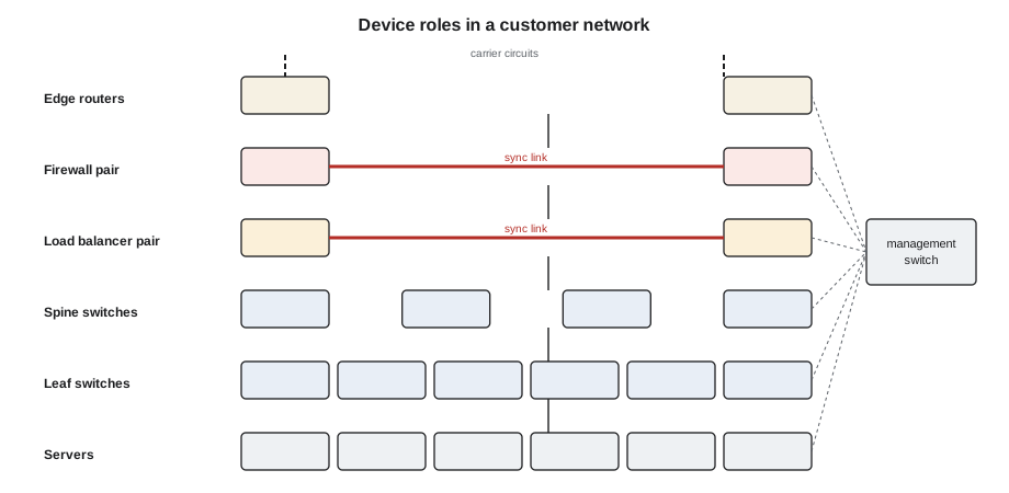
A switch connects devices on the same network and moves Ethernet frames between them by MAC address, as Lesson 3 describes. Data center switches come in a few roles. An access switch, often called a top-of-rack switch when it sits in the cabinet it serves, connects the servers in one cabinet or a few. A leaf switch in a spine-leaf fabric does the same job and also routes, as Lesson 6 explains. A spine switch connects only to leaves. A management switch connects the low-speed management ports of servers, power strips and other devices to the out-of-band network of Lesson 10.
Most data center switches today are fixed-configuration boxes one or two rack units high, with a row of optic cages on the front: 48 cages for 25 Gb/s optics plus 8 for 100 Gb/s uplinks on an older access switch, 32 or 64 cages for 400 or 800 Gb/s optics on a modern leaf or spine. Large networks also use modular chassis switches, several rack units high, with line cards that slide in and out of slots, supervisor cards that run the switch, and fabric cards behind them. In Hall A, Bayview Credit Union still runs a pair of chassis switches as its core; in the newer halls, fixed switches do every job.
Routers
A router connects different networks and moves packets between them by IP address. In a modern data center, the line between switches and routers has blurred: leaf and spine switches route as well as switch. Dedicated routers are still found at the edge of the network, where a customer's network meets its carriers or the internet. These edge routers hold large routing tables, run the routing sessions with carriers and often terminate the long-haul circuits that arrive through the meet-me room. A failed edge router can cut a customer off from the outside world even when everything inside is healthy, so edge routers are almost always installed in pairs with their links spread across both.
Firewalls and load balancers
A firewall sits in the path of traffic and decides, rule by rule, what may pass. Data center firewalls are usually appliances one to four rack units high, installed in pairs so that one can take over if the other fails. Between the pair runs a heartbeat or state-sync link, which keeps the standby firewall aware of every connection the active one is handling. That link is easy to mistake for a spare cable, and unplugging it can make both firewalls think they are active, which disrupts traffic. Carmen labels the Hall D sync cables in red and says so in every ticket that goes near them.
A load balancer spreads incoming requests across a group of servers so that no single server is overloaded and a failed server is taken out of rotation. Like firewalls, load balancers are usually paired and synchronized. From the floor, both look like servers with many network ports; the label and the owner's documentation are the only reliable way to know what a box is.
What is inside the box
Every network device, whatever its role, has the same few kinds of parts. Knowing which can be replaced while the device runs is a technician's most practical piece of knowledge about it.
| Part | What it does | Replace while running? |
|---|---|---|
| Power supplies | Usually two, one on each power feed; either can run the device | Yes, one at a time, if the other is healthy |
| Fan trays | Several modules that pull air through the box | Yes, quickly, one at a time; most switches shut down if a tray is out too long |
| Optics | Plug into the cages on the front | Yes; the link on that port drops |
| Line cards (chassis) | Hold ports | Often, but traffic on that card stops; owner decides |
| Supervisor cards (chassis) | Run the switch | Only the standby one, and only with the owner's engineer watching |
| Fixed switch itself | The whole box | No; replacing it is a planned change |
The short time limit on fan trays is easy to forget. Many switches allow only a minute or two with a fan tray removed before they shut down to protect themselves from overheating. Jamal unpacks the new tray, checks that it matches the airflow direction of the others, and has it in his hand before he releases the old one.
Airflow direction
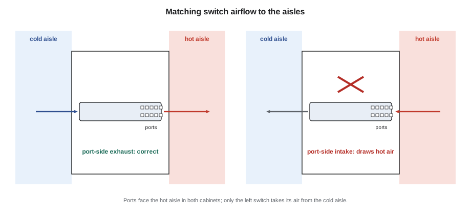
Network devices are cooled by fans that push air from one end of the box to the other. Unlike servers, which almost always draw air in at the front and exhaust at the back, switches come in both directions, because switches are often mounted with their ports facing the rear of the cabinet where the server cables arrive. A switch whose ports face the hot aisle needs to draw its air from the other end, the end facing the cold aisle.
Manufacturers label the two directions differently. Port-side intake means air enters at the end with the ports. Port-side exhaust means air leaves at the end with the ports. Some use front-to-back and back-to-front, which only makes sense if you know which end the manufacturer calls the front. Power supplies and fan trays carry the same marking, often a colored handle or an arrow, and every module in one switch must blow the same way. A switch with mixed modules fights itself and runs hot; a switch installed the wrong way round in a contained hall draws its cooling air from the hot aisle.
# Check a switch's airflow modules against the way it is mounted
ports_face = "hot aisle"           # which aisle the switch's ports face
modules = {
    "PSU1": "port-side exhaust",
    "PSU2": "port-side exhaust",
    "FAN1": "port-side exhaust",
    "FAN2": "port-side intake",    # a replacement tray shipped with the wrong direction
    "FAN3": "port-side exhaust",
}
needed = "port-side exhaust" if ports_face == "hot aisle" else "port-side intake"
print("Ports face the", ports_face, "-> every module must be", needed)
bad = [m for m, d in modules.items() if d != needed]
for m, d in modules.items():
    print(f"  {m:5} {d:18} {'ok' if d == needed else 'WRONG DIRECTION'}")
print("Install OK" if not bad else "Do not power on until these are changed: " + ", ".join(bad))Ports face the hot aisle -> every module must be port-side exhaust PSU1 port-side exhaust ok PSU2 port-side exhaust ok FAN1 port-side exhaust ok FAN2 port-side intake WRONG DIRECTION FAN3 port-side exhaust ok Do not power on until these are changed: FAN2
In this case the spare fan tray in the stores had been ordered for a different model with the opposite airflow. It fitted the slot, which is why the check matters: the label, not the fit, tells you the direction.
Power
Network devices are small loads compared with GPU servers, but they are the loads every other device depends on. A modern 64-port 800 Gb/s switch draws on the order of 2 kilowatts fully loaded with optics, and the optics are a large part of that. Every switch, router and firewall at Stonebridge has two power supplies, one on the A feed and one on the B feed, as DCT-130 describes for servers. Each power supply must be able to carry the whole device alone, so that a feed can be lost without the device noticing.
# Power budget for a leaf switch with optics, and the A/B feed check
base_w = 550                 # switch with fans, no optics (illustrative)
ports = 64
optic_w = 17                 # per 800G optic (illustrative)
psu_rating_w = 2400          # each of two power supplies
populated = 64
total = base_w + populated * optic_w
print(f"Switch load: {total} W with {populated} optics ({populated * optic_w} W of that is optics)")
print(f"Each PSU must carry it alone: {total} W of {psu_rating_w} W = {total / psu_rating_w:.0%}")
for feed in ("A", "B"):
    print(f"  If feed {'B' if feed == 'A' else 'A'} is lost, PSU on feed {feed} carries {total} W")
print("OK on one feed" if total <= psu_rating_w else "Over one PSU's rating: not redundant")Switch load: 1638 W with 64 optics (1088 W of that is optics) Each PSU must carry it alone: 1638 W of 2400 W = 68% If feed B is lost, PSU on feed A carries 1638 W If feed A is lost, PSU on feed B carries 1638 W OK on one feed
Optic power is the reason Corvid's network cabinets in Hall D draw more than some of the server cabinets in Hall A. Each 800 Gb/s optic draws as much as a small light bulb, and a full spine switch holds sixty-four of them.
Installing a switch
Racking a switch follows the rules of DCT-130: rails or brackets rated for the weight, the right U from the rack elevation, two people for anything heavy, and cable management planned before the first cord goes in. Network devices add a few steps. Check the airflow direction of every module against the cabinet's orientation before racking. Connect both power supplies to their correct feeds and confirm both show healthy. Connect the management port and the console port to the cabinet's management switch and console server, as Lesson 10 describes, before the device is powered on, so the owner's engineer can watch it boot. Record the serial number and the asset tag. Leave the data ports empty until the owner's engineer confirms the device is configured and asks for them to be connected.
Worked problem
A power supply swap in a live spine
The cloud provider reports that power supply 2 in spine switch b2-spine-05 has failed. The switch is carrying live traffic on its other supply.
Show solution
- Jamal checks the ticket: replace PSU2, part number given, provider's network engineer on the chat.
- At the switch he confirms PSU2 shows a fault light and PSU1 is healthy. He checks the replacement's airflow marking matches PSU1: both port-side exhaust.
- He tells the engineer he is about to remove PSU2, unplugs its power cord, releases the latch and slides it out.
- He slides the new unit in until the latch clicks, connects the cord to the B-feed strip, and waits for the healthy light.
- The engineer confirms both supplies show healthy in the switch's status, and Jamal closes the ticket with the old unit's serial number for the return.
Answer: The swap took four minutes and the switch never noticed, because PSU1 carried the load throughout.
Removing a device
Decommissioning a network device reverses the installation and needs the same care. The owner's engineer first confirms that no traffic depends on the device and that its configuration has been saved or wiped as the owner's policy requires. The technician then removes the data cords one at a time, checking each label against the decommissioning list, followed by the management and console cables and finally the power cords. Each removed cable is either taken out of the cabinet completely or recorded as a spare, and the port maps and console records are updated, because a stale record is how the next technician ends up tracing a cable to nowhere. The device goes to the owner's process for disposal or reuse, with its serial number recorded.
Common mistakes
MistakeAssuming a network box is a switch because it has many ports.
InsteadRead the label and the owner's records; firewalls and load balancers look similar.
MistakeUnplugging a firewall pair's sync link as a spare cable.
InsteadTreat any cable between two paired devices as live and ask.
MistakeFitting a fan tray or power supply with the opposite airflow.
InsteadCheck the marking on every module; all must blow the same way.
MistakeRemoving a fan tray before the new one is ready.
InsteadHave the replacement in hand; many switches shut down within minutes.
MistakeConnecting data ports as soon as a new switch is racked.
InsteadConnect power, management and console first; data ports when the owner asks.
Summary and key terms
- Switches connect devices on one network; leaf and spine switches also route; routers join networks at the edge.
- Firewalls and load balancers work in synchronized pairs; their sync links must never be unplugged without the owner.
- Power supplies, fan trays and optics are usually replaceable while the device runs, one at a time.
- Every module's airflow direction must match the others and the way the device faces the aisles.
- Each power supply must carry the whole device alone so that a feed can be lost.
- Install power, management and console first; data ports only when the owner asks.
- Top-of-rack switch
- An access switch in the cabinet whose servers it connects.
- Chassis switch
- A modular switch with line cards, supervisor cards and fabric cards in slots.
- Edge router
- A router where a network meets its carriers or the internet.
- Sync link
- The link between paired firewalls or load balancers that keeps them in step.
- Port-side intake
- Airflow that enters the device at the end with the ports.
- Port-side exhaust
- Airflow that leaves the device at the end with the ports.
Practice problems
Work each problem on paper first, then reveal the answer to check.
A switch's ports face the cold aisle. Which airflow should its modules have?
Show answer
Port-side intake, so air enters at the cold-aisle end.
Why are firewalls installed in pairs?
Show answer
So the standby can take over if the active one fails; the sync link keeps it ready.
A switch draws 1,640 W and each power supply is rated 1,500 W. Is it redundant?
Show answer
No; one supply alone cannot carry the load.
Name two parts that can usually be replaced while a fixed switch runs.
Show answer
Any two of: power supplies, fan trays, optics.
Lesson quiz · 5 questions
Score 60% or more to complete this lesson.
Create a free account to save your progress, take quizzes and earn a certificate.