
DCE-450 · Lesson 3 of 12 · 27 min
Electrical systems testing: switchgear, UPS, generators and load banks
The electrical system is the backbone of a data center, and most serious outages begin there. Commissioning it means proving, one layer at a time, that every conductor, breaker, relay, transformer, UPS, battery, generator and transfer switch does exactly what the design says, at full load and when things fail. This lesson works through electrical commissioning in the order it is usually done: acceptance testing of distribution equipment, protective device coordination, UPS and battery testing, generator and transfer testing, the load banks that make full-load testing possible before servers arrive, and the thermal and power quality measurements that provide objective evidence of a healthy installation.
Acceptance testing of distribution equipment
Before anything is energized, switchgear, switchboards, transformers, busway and cables receive acceptance tests. In North America the reference is ANSI/NETA ATS, the InterNational Electrical Testing Association's Standard for Acceptance Testing Specifications, which lists the visual, mechanical and electrical tests for each type of equipment and the values that indicate acceptable condition. Testing is done by certified technicians, usually from an independent testing firm, and their reports become the baseline for maintenance testing to the companion standard, NETA MTS, for the rest of the facility's life (Lesson 8).
Typical acceptance tests include:
- Visual and mechanical inspection: nameplate data against drawings, physical damage, anchorage, clearances, correct and tight bolted connections (checked with a calibrated torque wrench or a low-resistance ohmmeter), and correct operation of mechanical interlocks and racking mechanisms.
- Insulation resistance: a DC test voltage (for example 1,000 V for 480 V or 600 V equipment) applied between each phase and ground and between phases, with readings in megohms compared against the standard's minimum values and against other phases.
- Contact and connection resistance: a micro-ohmmeter measures the resistance across breaker contacts and bus joints; a reading much higher than similar joints points to a loose or contaminated connection.
- Transformer tests: turns ratio, winding resistance, insulation resistance and, for liquid-filled units, dielectric and gas analysis of the oil.
- Breaker trip tests: primary injection (passing high current through the breaker to verify it trips within its time-current curve) or secondary injection into the trip unit, depending on breaker type.
- Protective relay testing: verifying that each relay is set to the coordination study values and operates its breaker.
- Ground fault protection and grounding system tests: verifying ground fault settings and measuring the resistance of the grounding electrode system.
A useful rule when reviewing results is that consistency matters as much as absolute values. Three phases of a feeder should read alike; if two read 5,000 MΩ and one reads 50 MΩ, the odd one is suspect even if it passes the minimum.
Protective device settings and coordination
A coordination study, prepared by the electrical engineer, calculates fault currents throughout the system and selects settings so that the breaker nearest a fault trips first, leaving the rest of the system in service. In a data center, a fault on one rack PDU feeder should trip only that feeder, not the PDU main, and certainly not the UPS output breaker. The study also produces the arc-flash incident energy labels required before workers approach energized equipment (Lesson 2).
Commissioning verifies that the settings in the field match the study. This sounds trivial but is a frequent source of findings: breakers ship with factory default settings, technicians enter values for the wrong breaker, and settings are changed during start-up and not changed back. A settings verification step, in which every adjustable trip unit and relay is read out and compared with the approved study, is part of every electrical commissioning plan, and the final settings files go into the turnover package.
UPS testing
The uninterruptible power supply is tested at the factory (Level 1), started up by the vendor (Level 3), and then put through functional tests on site with a load bank (Level 4). A typical UPS functional test sequence includes:
- Steady-state performance at 25 %, 50 %, 75 % and 100 % load: output voltage regulation, efficiency, input current distortion and output waveform quality, recorded with a power quality analyzer.
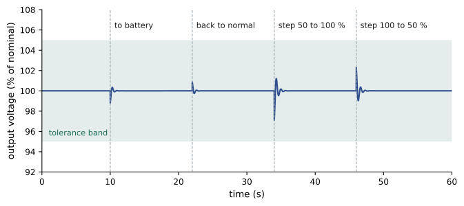
- Step load response: applying and removing large load steps (for example 0 to 50 % and 50 to 100 %) and checking the output voltage transient against the manufacturer's specification. IEC 62040-3 classifies UPS dynamic performance; most double-conversion UPS meet its most stringent class, with transients that stay within limits that IT power supplies tolerate.
- Transfers: from normal to battery (by opening the UPS input), back to normal, to static bypass and back, and through the maintenance bypass, verifying that the load never sees an interruption.
- Module or system failure: failing one module of a modular or parallel system to show the remaining modules carry the load (Lesson 2 example).
- Battery discharge: running the UPS on battery at design load until the batteries reach end voltage, to verify runtime.
- Alarms and monitoring: verifying that every alarm reaches the UPS display, the electrical power monitoring system (EPMS) and the building management system (BMS) correctly.
Battery testing
Valve-regulated lead-acid (VRLA) batteries, flooded lead-acid batteries and, increasingly, lithium-ion batteries are tested in several ways. During installation, each jar or module is checked for voltage and connection resistance, and torque is verified on every intercell connector. During functional testing, a discharge test at the design load proves the battery delivers its rated runtime. For lead-acid batteries, IEEE 450 (flooded) and IEEE 1188 (VRLA) give test and maintenance procedures, including capacity tests and correction for temperature, because a cold battery delivers less capacity and a hot one ages faster.
Worked problem
Checking battery runtime
A UPS is designed to carry 1,200 kW for 5 minutes at end of battery life. On a new battery, discharge at 1,200 kW lasts 7.2 minutes. The battery room was at 20 °C, and the manufacturer's correction factor for capacity at 20 °C relative to the rated 25 °C is 0.96. Batteries are replaced when capacity falls to 80 % of rated. Does the battery meet the design?
Show solution
- Correct the measured runtime to the rated temperature: 7.2 / 0.96 = 7.5 minutes at 25 °C.
- At end of life the battery delivers 80 % of its rated capacity. Runtime does not scale exactly with capacity, but as a first estimate: 0.80 × 7.5 = 6.0 minutes.
- Compare with the requirement: 6.0 minutes is more than 5 minutes.
Answer: The battery meets the design with about one minute of margin at end of life. The test record should state the load, duration, room temperature, end voltage and each string's performance; a string that reached end voltage early would point to a weak jar even if the overall runtime passed.
Lithium-ion batteries need a different approach. They are monitored by a battery management system that reports cell voltages, temperatures and state of charge, and their commissioning includes verifying the battery management system's alarms and protective trips, the fire detection and suppression or ventilation arrangements required by the fire code, and the manufacturer's thermal runaway protections.
Generators and transfer systems
Standby diesel generators are the long-duration backup for utility failure. Commissioning covers each generator alone, then the generators in parallel, then the transfer system that connects them to the building.
- Individual generator tests: cold start and time to rated voltage and frequency; load acceptance in steps up to full load; full-load run for an extended period while monitoring temperatures, pressures, exhaust and fuel consumption; load rejection; and all engine safety shutdowns (low oil pressure, high coolant temperature, overspeed), which are tested by simulating each condition.
- Paralleling: synchronizing and closing onto a common bus, load sharing between units within a few percent, and the response when one generator fails while the others carry the load.
- Transfer: automatic transfer switches or paralleling switchgear sense loss of utility, signal the generators to start, transfer the load within the required time, and retransfer to utility after it returns and stabilizes, followed by a cool-down run.
- Fuel system: transfer pumps, day tank level controls, leak detection and fuel polishing, and verification of on-site fuel storage against the required runtime.
In the United States, emergency and legally required standby generators are governed by NFPA 110, Standard for Emergency and Standby Power Systems, referenced by NFPA 70 (the National Electrical Code) and NFPA 101. It classifies systems by start time (Type 10 must restore power within 10 seconds) and sets acceptance testing (including a full-load test) and periodic testing. Data center standby generators that serve only IT load are usually tested to similar procedures by owner choice.
Generator load acceptance deserves attention. When a large block of load is applied to a diesel generator, its speed, and therefore frequency, dips, and the voltage regulator must recover the voltage. ISO 8528-5 defines performance classes for these transients. Engines with turbochargers cannot accept full load in one step, so transfer schemes add load in stages, and the UPS systems, which see the generator as their input, are often set to walk in their input load over several seconds. The functional test verifies that the frequency and voltage dips on each step stay within the specification and that UPS rectifiers do not reject the generator power.
Load banks
A new data center has no servers when it is commissioned, yet every system must be proven at design load. Load banks provide that load. Resistive load banks convert electrical power to heat through resistor elements and fans; reactive load banks add inductive load so that generators and transformers can be tested at their rated power factor (typically 0.8). In data halls, small rack-mounted or floor-standing load banks that mimic servers are distributed across the white space so that the cooling system sees heat where the IT equipment will be, which is essential for testing airflow and containment (Lesson 4).
Load bank testing is a significant logistical and environmental undertaking: banks must be rented, delivered, cabled, controlled and cooled, and the generators that test them burn substantial fuel.
# Load-bank test plan for four 2.5 MW standby generators (each tested separately, then in parallel)
gens, rating_kW = 4, 2500
steps = [(0.25, 0.5), (0.50, 0.5), (0.75, 0.5), (1.00, 2.0)]   # (fraction of rating, hours)
sfc = {0.25: 0.33, 0.50: 0.28, 0.75: 0.265, 1.00: 0.26}        # L of diesel per kWh at each load
co2_per_L = 2.68                                                # kg CO2 per L of diesel

energy = fuel = 0.0
for frac, h in steps:
    kWh = gens * rating_kW * frac * h
    energy += kWh
    fuel += kWh * sfc[frac]
print(f"Per-unit test: {sum(h for _, h in steps):.1f} h; all {gens} units: {energy:,.0f} kWh into the load banks")
print(f"Diesel used: {fuel:,.0f} L; CO2 emitted: {fuel * co2_per_L / 1000:.1f} t")
print(f"Peak heat rejected by load banks in the parallel test: {gens * rating_kW / 1000:.1f} MW")
print(f"Full-load fuel rate per generator: {rating_kW * sfc[1.0]:,.0f} L/h")Per-unit test: 3.5 h; all 4 units: 27,500 kWh into the load banks Diesel used: 7,306 L; CO2 emitted: 19.6 t Peak heat rejected by load banks in the parallel test: 10.0 MW Full-load fuel rate per generator: 650 L/h
For four 2.5 MW generators, the test sequence uses over 7,000 L of diesel, emits about 20 t of CO₂, and at the parallel full-load step rejects 10 MW of heat from load banks that must sit outdoors with clear exhaust paths. Planning therefore covers where the load banks go, how their heat and noise affect neighbors, cable routes and connection points (permanent load bank connection cabinets designed into the switchgear simplify this greatly), fuel delivery, and how to combine tests so that each kilowatt-hour proves as much as possible. Some projects test generator, UPS and cooling together in one long run rather than repeating full-load runs for each.
Thermal imaging and power quality
Two measurements turn a functional test into objective evidence. Infrared thermography of every bolted connection, breaker and busway joint while the system carries substantial load (at least 40 % of rating, and ideally design load) finds loose or undersized connections, which show as hot spots relative to similar components. A temperature rise of a few degrees over comparable connections warrants investigation; a rise of tens of degrees calls for immediate repair. Because a thermographic survey can check hundreds of connections in an hour, it compensates for the weakness of sampling for random defects (Lesson 2).
Power quality analyzers record voltage, current, frequency, harmonics and transients on key buses throughout testing. They provide the proof that a transfer caused no interruption, quantify voltage dips during generator load steps, and measure harmonic distortion from UPS rectifiers against IEEE 519 or the utility's requirements. Their recordings are attached to the test scripts as evidence.
Organizing electrical commissioning
Electrical commissioning proceeds roughly from source to load: utility service and medium-voltage switchgear, transformers, low-voltage switchgear, generators, UPS, distribution and finally rack power. Each step requires the upstream equipment to be energized and stable, which drives the construction schedule. A well-run project agrees an energization sequence early, aligns it with the utility's connection date, and plans for load banks and power quality recorders to be available at each functional testing stage.
Common mistakes
MistakeAccepting breakers with factory default trip settings.
InsteadRead out every adjustable device and compare it with the coordination study.
MistakeJudging insulation resistance only against the minimum value.
InsteadCompare phases and similar equipment; an outlier is suspect even if it passes.
MistakeRunning a battery discharge test without recording temperature.
InsteadRecord room and cell temperatures and correct capacity to the rated temperature.
MistakeApplying full building load to a generator in a single step.
InsteadStage the load and verify frequency and voltage dips against the specification.
MistakeDoing thermography at light load.
InsteadScan connections at substantial load, ideally design load, during functional testing.
Summary and key terms
- Distribution equipment is acceptance tested to NETA ATS; results become the maintenance baseline.
- Field settings must match the coordination study; verify every adjustable device.
- UPS functional tests cover steady state, load steps, transfers, module failure, battery discharge and alarms.
- Battery capacity tests must be corrected for temperature and checked against end-of-life capacity.
- Generators are tested alone, in parallel and with the transfer system, including staged load acceptance.
- Load banks make full-load testing possible, with large fuel, heat and logistics demands.
- Thermography under load and power quality recordings provide objective evidence.
- NETA ATS
- The acceptance testing standard for electrical power equipment.
- Insulation resistance test
- A DC test measuring the resistance of insulation between conductors and ground.
- Primary injection
- Testing a breaker by passing high current through its main conductors.
- Coordination study
- An analysis selecting protective device settings so the nearest device clears a fault.
- Step load test
- Applying a sudden load change to measure transient response.
- Discharge test
- Running a battery at load to its end voltage to measure capacity or runtime.
- Load acceptance
- A generator's ability to pick up load blocks within frequency and voltage limits.
- Resistive load bank
- A device that converts electrical power to heat to load a source for testing.
- Reactive load bank
- A load bank that adds inductive load to test at rated power factor.
- Thermography
- Infrared imaging to find abnormally hot components.
Practice problems
Work each problem on paper first, then reveal the answer to check.
What standard governs acceptance testing of switchgear and transformers in North America?
Show answer
ANSI/NETA ATS.
Three phases read 4,800, 5,200 and 60 MΩ, all above the minimum. What should you do?
Show answer
Investigate the 60 MΩ phase; it is far out of line with the others.
Why must field relay settings be verified?
Show answer
Devices ship with defaults or are set wrongly, which can cause loss of coordination or nuisance trips.
List four UPS functional tests.
Show answer
For example: steady-state at several loads, step load, transfer to battery and bypass, module failure, battery discharge, alarms.
A battery runs 6.0 minutes at 20 °C with a correction factor 0.96. What is the runtime corrected to 25 °C?
Show answer
6.0 / 0.96 = 6.25 minutes.
Why are generator loads added in steps?
Show answer
Turbocharged engines cannot accept full load at once without excessive frequency and voltage dips.
Why are reactive load banks used for generators?
Show answer
To test at rated power factor, typically 0.8, not just at unity.
From the output, how much diesel does the load bank test use?
Show answer
About 7,300 L.
At what load should thermography be done?
Show answer
Substantial load, at least about 40 % and ideally design load.
What does a power quality analyzer prove during a UPS transfer test?
Show answer
That the output had no interruption and stayed within voltage limits.
Lesson quiz · 5 questions
Score 60% or more to complete this lesson.
Create a free account to save your progress, take quizzes and earn a certificate.