
DCE-320 · Lesson 4 of 12 · 29 min
Optical fiber in depth: loss, dispersion and wavelengths
Lesson 2 introduced fiber as a glass core and cladding that guide light, and compared multimode and single-mode grades by reach. A designer who must choose fiber types for a twenty-year plant, explain why a link fails, or decide whether a new transceiver will work over existing cabling needs to look deeper: at where loss comes from, how pulses spread, why particular wavelengths are used, how bends and reflections affect modern high-speed optics, and how several signals can share one fiber. This lesson covers those physical foundations.
Light in glass
Light travels more slowly in glass than in a vacuum, by the factor of the refractive index, about 1.47 for the silica used in fiber. That sets the propagation delay of every fiber link: about 4.9 µs per kilometer, or 4.9 ns per meter. In a data center this is small compared with switch and software delays, but between data centers, and in large AI training clusters where thousands of processors wait on each other, it adds up.
The core has a slightly higher refractive index than the cladding, typically by about 0.3% to 1%, and light striking the boundary at a shallow enough angle is totally reflected. The range of angles the fiber accepts is described by its numerical aperture (NA): about 0.2 for 50 µm multimode fiber and about 0.12 to 0.14 for single-mode. A larger NA collects light more easily from cheap sources but supports more modes.
Where loss comes from
The attenuation of a fiber has several causes:
- Rayleigh scattering: tiny variations in the density of the glass, frozen in when it was drawn, scatter light in all directions. Scattering is proportional to \(1/\lambda^{4}\), so it falls rapidly at longer wavelengths. It is the dominant loss in modern fiber.
- Absorption: by the glass itself at long wavelengths (infrared absorption, rising beyond about 1,600 nm), and by impurities. Hydroxyl (OH) ions from water once caused a large "water peak" at 1,383 nm; low-water-peak fiber (ITU-T G.652.D) has almost eliminated it, opening the whole range from 1,260 nm to 1,625 nm for use.
- Bending: when the fiber bends too tightly, some light escapes the core. Macrobends are visible bends below the minimum bend radius; microbends are tiny distortions from pressure, such as a fiber crushed by a cable tie or squeezed in a cold, shrinking jacket.
- Connectors and splices: the largest losses in a short data center link, from misalignment of cores, gaps, angles and contamination (Lesson 6).
# Rayleigh scattering scales as 1 / wavelength**4.
# Scale a measured 0.33 dB/km at 1310 nm to other wavelengths.
ref_nm, ref_loss = 1310, 0.33
for nm in (850, 1310, 1550):
    loss = ref_loss * (ref_nm / nm) ** 4
    print(f"{nm:5d} nm  scattering loss about {loss:.2f} dB/km")

# Chromatic dispersion: pulse spread = D * spectral width * length
def spread_ps(D, width_nm, km):
    return D * width_nm * km

for band, D in (("O-band 1310 nm", 0.5), ("C-band 1550 nm", 17.0)):
    t = spread_ps(D, 0.1, 10)
    print(f"{band}: spread over 10 km = {t:.1f} ps")

symbol_ps = 1e12 / 53.125e9   # 106.25 Gb/s PAM4 lane = 53.125 GBd
print(f"Symbol period at 53.125 GBd = {symbol_ps:.1f} ps")850 nm scattering loss about 1.86 dB/km 1310 nm scattering loss about 0.33 dB/km 1550 nm scattering loss about 0.17 dB/km O-band 1310 nm: spread over 10 km = 0.5 ps C-band 1550 nm: spread over 10 km = 17.0 ps Symbol period at 53.125 GBd = 18.8 ps
The result explains the wavelengths used. Multimode fiber works at 850 nm, where cheap vertical-cavity surface-emitting lasers (VCSELs) are available, accepting about 2 to 3 dB/km because data center links are short. Single-mode links use the O-band near 1,310 nm, where loss is about 0.3 to 0.4 dB/km and, crucially, chromatic dispersion is nearly zero; long-haul links use the C-band near 1,550 nm, where loss is lowest and optical amplifiers work.
| Cable type | Wavelength | Maximum attenuation (TIA-568.3) |
|---|---|---|
| Multimode (OM3, OM4, OM5) | 850 nm | 3.0 dB/km |
| Multimode (OM3, OM4, OM5) | 1,300 nm | 1.5 dB/km |
| Single-mode, inside plant | 1,310 and 1,550 nm | 1.0 dB/km |
| Single-mode, outside plant | 1,310 and 1,550 nm | 0.5 dB/km |
Dispersion
Dispersion spreads each pulse in time, so that at high symbol rates neighboring symbols blur together. There are three kinds:
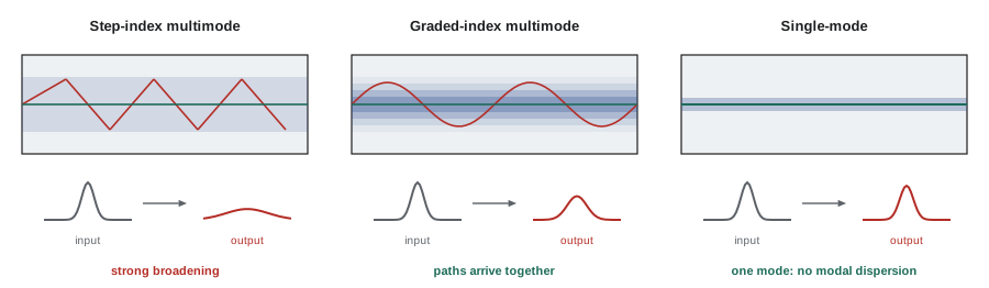
- Modal dispersion, in multimode fiber only: different modes travel different path lengths. Graded-index fiber compensates by making the outer parts of the core faster. The result is expressed as effective modal bandwidth (EMB), a bandwidth-length product: OM3 is specified at 2,000 MHz·km at 850 nm, OM4 at 4,700 MHz·km, and OM5 at 4,700 MHz·km at 850 nm and 2,470 MHz·km at 953 nm, so that it supports several wavelengths.
- Chromatic dispersion, in all fiber: different wavelengths travel at slightly different speeds, and every real laser emits a small range of wavelengths. It is measured by the dispersion coefficient \(D\) in ps/(nm·km). Standard single-mode fiber has \(D \approx 0\) near 1,310 nm and about 17 ps/(nm·km) at 1,550 nm.
- Polarization mode dispersion (PMD): the two polarizations of light travel at slightly different speeds in imperfect fiber. It matters on long, high-speed links, rarely within a building.
Worked problem
How far will multimode go?
A rough guide is that a link needs a bandwidth of at least about 0.7 times the symbol rate. For a 26.5 GBd lane (as in 100GBASE-SR4 with 25 Gb/s NRZ lanes after coding), what is the modal-bandwidth-limited reach on OM3 and on OM4?
Show solution
- Required bandwidth: \(0.7 \times 26.5 = 18.6\) GHz = 18,600 MHz.
- OM3: \(2{,}000 / 18{,}600 = 0.108\) km = 108 m.
- OM4: \(4{,}700 / 18{,}600 = 0.253\) km = 253 m.
Answer: About 108 m on OM3 and 250 m on OM4 from modal bandwidth alone. The standard reaches (70 m on OM3 and 100 m on OM4) are shorter because chromatic dispersion of the VCSEL's spectrum, connector loss and transceiver penalties also count. The ratio between fiber grades follows the bandwidth, which is why OM4 reaches further.
Single-mode fiber types and bend-insensitive fiber
ITU-T recommendations define single-mode fiber types:
- G.652.D: standard low-water-peak single-mode fiber, the default for data centers and most networks.
- G.657.A1 and A2: bend-insensitive fibers, compatible with G.652.D but with much lower bend loss. A trench of lower refractive index around the core holds light in at tight bends: G.657.A1 tolerates a 10 mm bend radius and A2 7.5 mm.
- G.654: low-loss, large-effective-area fiber for submarine and long-haul links.
- G.655 and G.656: non-zero dispersion-shifted fibers for dense wavelength-division multiplexing over long distances.
Bend-insensitive fiber is now normal for data center cabling, both single-mode (G.657.A1 or A2) and bend-insensitive multimode. It tolerates tight routing in cassettes, cable managers and congested trays. It does not remove the need to follow cable bend radius limits, which protect the cable's structure as well as the light; the cable's minimum bend radius during installation is typically 20 times its outer diameter, and 10 times after installation.
Cable constructions also matter. Data center trunk cables increasingly use 200 µm coated fibers in place of 250 µm, and rollable ribbon, in which fibers are bonded intermittently so the ribbon can be rolled into a compact bundle for high fiber counts yet spread flat for fast mass fusion splicing. A 3,456-fiber cable that once needed a 40 mm diameter can now fit in about 30 mm.
Reflections and connector polish
Every connection reflects a little light back toward the transmitter. The strength of the reflection is the reflectance (in dB, negative; more negative is better), or equivalently the return loss (the same magnitude, positive). Reflections matter because they can disturb the laser, and because two reflections in a link create a weak delayed copy of the signal at the receiver, which acts as noise.
- Physical contact (PC) and ultra physical contact (UPC) connectors have a domed end face polished flat to the fiber, with reflectance of about −40 to −50 dB.
- Angled physical contact (APC) connectors are polished at 8°, so reflected light is directed out of the core into the cladding, giving reflectance of −60 dB or better. They are color-coded green.
Multi-level signaling such as PAM4, used at 50 Gb/s per lane and above, has less margin than the older two-level NRZ signaling, so it is more sensitive to reflections. Single-mode parallel optics such as 400GBASE-DR4 and 800G DR8 therefore specify a limit on the number and reflectance of connections, and many designers now use MPO-APC connectors for single-mode trunks. APC and UPC connectors must never be mated with each other: the angled and flat faces leave an air gap that causes high loss and can damage both.
Worked problem
Reflectance in decibels
What fraction of the incident power does a UPC connector reflect at −50 dB, and an APC connector at −65 dB?
Show solution
- UPC: \(10^{-50/10} = 10^{-5}\), 0.001%.
- APC: \(10^{-65/10} = 3.2 \times 10^{-7}\), 0.00003%.
Answer: The APC connector reflects about 30 times less light. Both are tiny fractions, but a high-speed receiver sees the sum of reflections from every connection, and the double reflections between pairs of them.
Using more than one wavelength
A fiber can carry several signals at once on different wavelengths, combined and separated by optical filters. This is wavelength-division multiplexing (WDM), and in the data center it lets one fiber pair carry several lanes, reducing fiber counts:
- Coarse WDM (CWDM): wavelengths 20 nm apart, such as 1,271, 1,291, 1,311 and 1,331 nm. 100G CWDM4 and 400GBASE-FR4 use four CWDM wavelengths on one duplex single-mode pair for 2 km.
- LAN-WDM: four wavelengths about 4.5 nm apart near 1,310 nm, used in LR4 optics for 10 km.
- Shortwave WDM and bidirectional (BiDi) optics on multimode fiber: two to four wavelengths between about 850 nm and 940 nm. 400GBASE-SR4.2 sends two wavelengths in opposite directions on each fiber of an 8-fiber MPO, reaching 70 m on OM3, 100 m on OM4 and 150 m on OM5. OM5 was designed for these applications.
- Dense WDM (DWDM): wavelengths about 0.4 or 0.8 nm apart near 1,550 nm, with optical amplifiers, for data center interconnect between buildings and long-haul links (Lesson 11).
The design choice is between parallel fibers (one lane per fiber, MPO connectors, cheaper optics, many fibers) and WDM (several lanes per fiber, duplex LC connectors, more expensive optics, fewer fibers). Lesson 5 compares the transceivers that use each.
Latency and hollow-core fiber
Because light in silica travels at about two-thirds of its speed in a vacuum, each kilometer adds about 4.9 µs. Hollow-core fiber guides light through an air-filled core surrounded by microstructured glass, so light travels at nearly its vacuum speed, about 3.3 µs per kilometer, roughly 30% less delay, with very low nonlinearity and dispersion. Hollow-core fiber is being deployed by some operators between data centers in a region, where the lower latency allows sites to be further apart while behaving like one large facility. It needs special splicing and connectors and is not yet a general-purpose replacement for standard fiber.
Worked problem
Latency between campuses
Two data center buildings are linked by a 60 km fiber route. Compare the one-way propagation delay over standard fiber (4.9 µs/km) and hollow-core fiber (3.35 µs/km).
Show solution
- Standard: \(60 \times 4.9 = 294\) µs.
- Hollow-core: \(60 \times 3.35 = 201\) µs.
- Difference: 93 µs one way, 186 µs round trip.
Answer: 294 µs and 201 µs. For a latency budget of, say, 500 µs round trip, standard fiber allows sites about 51 km apart by route; hollow-core about 75 km.
Common mistakes
MistakeAssuming single-mode fiber has no dispersion.
InsteadIt has no modal dispersion, but chromatic dispersion matters at high speeds outside the O-band.
MistakeMating APC and UPC connectors.
InsteadNever mix them; the angled and flat faces leave a gap and can damage both.
MistakeRelying on bend-insensitive fiber to ignore cable bend radius limits.
InsteadFollow the cable's installed and pulling bend radius, which protects its structure.
MistakeUsing typical attenuation in loss budgets.
InsteadUse the maximum cabled attenuation from the standard or the manufacturer.
MistakeChoosing OM5 for every new multimode plant by default.
InsteadOM5 helps only with shortwave WDM and BiDi optics; OM4 is otherwise equivalent.
Summary and key terms
- Light in fiber travels at about 1/1.47 of its vacuum speed: 4.9 µs per km.
- Rayleigh scattering dominates loss and falls as 1/λ⁴; bends and connectors add loss.
- Multimode uses 850 nm VCSELs; single-mode uses the O-band near zero dispersion and the C-band for long haul.
- Modal bandwidth limits multimode reach; chromatic dispersion limits single-mode reach at high speed.
- APC connectors reduce reflections, which matter more for PAM4 optics.
- WDM puts several lanes on one fiber; hollow-core fiber reduces latency by about 30%.
- Numerical aperture
- A measure of the range of angles a fiber accepts.
- Rayleigh scattering
- Scattering by tiny density variations in glass, proportional to 1/λ⁴.
- Effective modal bandwidth
- The bandwidth-length product of a multimode fiber.
- Chromatic dispersion
- Pulse spreading because different wavelengths travel at different speeds.
- Bend-insensitive fiber
- Fiber designed to lose little light at tight bends (G.657).
- Reflectance
- The ratio of reflected to incident power at a connection, in dB.
- APC
- Angled physical contact connector polish, at 8°.
- CWDM
- Coarse wavelength-division multiplexing with 20 nm spacing.
- VCSEL
- Vertical-cavity surface-emitting laser, the usual multimode source.
- Hollow-core fiber
- Fiber that guides light in an air core, reducing latency.
Practice problems
Work each problem on paper first, then reveal the answer to check.
One-way delay over 12 km of standard fiber?
Show answer
12 × 4.9 = 58.8 µs.
If loss at 1,310 nm is 0.35 dB/km, estimate Rayleigh loss at 1,550 nm.
Show answer
0.35 × (1310/1550)⁴ ≈ 0.18 dB/km.
Why is the O-band used for data center single-mode PAM4 links?
Show answer
Chromatic dispersion is near zero there.
Pulse spread with D = 17 ps/(nm·km), 0.2 nm width, 20 km?
Show answer
68 ps.
Modal-bandwidth reach on OM4 for a 10 GHz requirement?
Show answer
4,700/10,000 = 0.47 km.
What does a G.657.A2 fiber tolerate?
Show answer
A bend radius of 7.5 mm with low loss.
Fraction reflected at −40 dB?
Show answer
0.01%.
What color identifies APC connectors?
Show answer
Green.
What do CWDM4 and FR4 optics have in common?
Show answer
Four CWDM wavelengths on one duplex single-mode pair.
Round-trip saving with hollow-core fiber on a 30 km route?
Show answer
2 × 30 × 1.55 = 93 µs.
Lesson quiz · 5 questions
Score 60% or more to complete this lesson.
Create a free account to save your progress, take quizzes and earn a certificate.