
DCE-320 · Lesson 2 of 12 · 30 min
Copper and fiber media selection
Every link in a data center needs a medium: twisted-pair copper, twinaxial copper, multimode fiber or single-mode fiber. The choice depends on the link's length and speed, on the optics or transceivers the network team will buy, on the cost of the whole channel (cable plus transceivers, which usually dominate), on power and heat at the switch, and on how long the cabling must last. Getting it wrong is expensive: a plant that cannot carry the next generation of speeds must be re-cabled while the facility is live.
This lesson reviews how each medium carries signals, the categories and grades defined by the standards, the reach of common Ethernet applications on each, and a method for choosing media for a new facility. DCE-210 introduced optics and the naming of Ethernet interfaces; here the focus is on the cabling plant.
Balanced twisted-pair copper
Twisted-pair cable carries signals as the voltage difference between the two conductors of each pair (balanced transmission). Twisting makes any interference induce nearly equal voltages in both conductors, which cancel at the receiver, and different twist rates in the four pairs reduce crosstalk between them. Performance is specified by category, each tested up to a maximum frequency:
| Category | Frequency | Typical data center use | Reach |
|---|---|---|---|
| Category 6 | 250 MHz | 1 Gb/s; 10GBASE-T only on short links | 100 m at 1 Gb/s; about 37–55 m at 10 Gb/s |
| Category 6A | 500 MHz | 10GBASE-T, management networks, Wi-Fi access points, PoE | 100 m channel at 10 Gb/s |
| Category 8 | 2000 MHz | 25GBASE-T and 40GBASE-T between nearby cabinets | 30 m channel with two connectors |
Category 6A is the minimum recommended by TIA-942 for new horizontal copper cabling. It is used for 1 and 10 Gb/s server connections in enterprise halls, and everywhere for out-of-band management networks, building systems, security cameras and access points. Category 8 was designed for switch-to-server links in ToR and EoR layouts, but 25GBASE-T and 40GBASE-T saw little adoption because twinax and fiber do the same job with less power and latency.
Copper cables are built as unshielded (U/UTP), with an overall foil (F/UTP), or with individually foiled pairs (U/FTP or S/FTP). Shielded cables resist interference better and allow tighter bundling, but the shield must be bonded at the patch panel to the telecommunications bonding system (TIA-607), and they are stiffer and larger. Category 6A cable is roughly 6 to 8 mm in diameter, noticeably larger than Category 6, which matters for tray fill (Lesson 8).
Bundling also matters thermally: when copper carries Power over Ethernet (PoE) at the higher power levels of IEEE 802.3bt (up to about 90 W at the source), the current heats the conductors, and large bundles must be derated or split, as with power conductors in an electrical raceway.
Twinaxial copper and active cables
For the shortest high-speed links, inside a cabinet or to the next cabinet, the network team usually buys direct-attach copper (DAC): a twinaxial cable with a transceiver-shaped plug molded on each end. Passive DACs reach about 3 m at 100 Gb/s per lane and less at 200 Gb/s per lane; active electrical cables (AECs) with signal-conditioning chips reach about 5 to 7 m. Active optical cables (AOCs) have optics built into the plugs and a fiber between them, reaching tens of meters.
DACs, AECs and AOCs are not part of the structured cabling plant: they are point-to-point equipment cords, bought with the network equipment and replaced with it. The structured plant must still provide pathways and cable management for them, and the designer must know which links will use them, because a link that leaves the cabinet row usually cannot.
How optical fiber works
An optical fiber is a glass core surrounded by a glass cladding with a slightly lower refractive index. Light launched into the core is guided by total internal reflection at the core-cladding boundary. Both have an outer diameter of 125 µm; the core is 50 µm in data center multimode fiber and about 9 µm in single-mode fiber. A 250 µm (or 200 µm in reduced-diameter designs) acrylate coating protects the glass, and cables add buffers, strength members and jackets.
Two properties limit how far a signal can travel:
- Attenuation: the loss of optical power along the fiber, in dB/km, caused mostly by scattering in the glass. It is lowest at 1550 nm (about 0.2 dB/km in cabled single-mode fiber, although specifications allow more) and higher at 1310 nm and 850 nm.
- Dispersion: the spreading of each light pulse as it travels, which blurs successive bits into each other. In multimode fiber the main cause is modal dispersion: light travels along many paths (modes) of slightly different lengths. Graded-index multimode fiber reduces this by grading the refractive index so that longer paths are faster, and the quality of that grading is measured as the fiber's effective modal bandwidth (EMB) in MHz·km. Single-mode fiber carries only one mode, so modal dispersion disappears, and only much smaller chromatic dispersion remains.
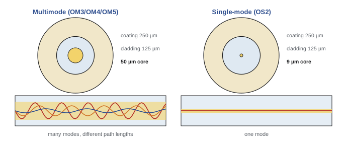
Because multimode fiber has a large core, it can be used with inexpensive vertical-cavity surface-emitting lasers (VCSELs) at 850 nm, which is why multimode optics have historically been cheaper. Single-mode optics need more precise lasers and alignment, but high-volume production for hyperscale data centers has narrowed the price gap, and single-mode reach is far longer.
Fiber grades
The standards define multimode grades by bandwidth and single-mode grades by attenuation and dispersion:
| Grade | Core | Key specification | Jacket color (typical) | Use |
|---|---|---|---|---|
| OM3 | 50 µm | EMB 2000 MHz·km at 850 nm | Aqua | Older and legacy multimode plant |
| OM4 | 50 µm | EMB 4700 MHz·km at 850 nm | Aqua or violet | Short-reach multimode links up to about 100 m |
| OM5 | 50 µm | OM4 performance plus bandwidth specified from 850 to 953 nm | Lime green | Short-wavelength division multiplexing |
| OS2 | 9 µm | Low water peak; about 0.4 dB/km at 1310 nm and 0.3 dB/km at 1550 nm | Yellow | All single-mode links, inside and outside plant |
Standard cabling specifications allow higher maximum attenuation than these typical figures. For example, TIA-568.3 allows 3.5 dB/km at 850 nm for multimode cable and, for single-mode, 1.0 dB/km for inside plant cable and 0.5 dB/km for outside plant cable. A loss budget calculated with the standard's maximums is conservative; one using the manufacturer's guaranteed values is tighter but still defensible (Lesson 6).
Bend-insensitive fibers (ITU-T G.657 for single-mode, and bend-insensitive multimode) lose much less light in tight bends. They are now standard in data center cables because the plant is full of small-radius routing in panels and cabinets. Fiber also comes in reduced-coating (200 µm) versions that allow more fibers in a smaller cable.
Reach of common applications
For each Ethernet interface, the IEEE 802.3 standard sets a maximum reach on each fiber grade together with a maximum channel insertion loss. These are the most important numbers for media selection:
| Interface | Fibers | OM3 | OM4 | Single-mode |
|---|---|---|---|---|
| 10GBASE-SR | 2 | 300 m | 400 m | — |
| 100GBASE-SR4 | 8 | 70 m | 100 m | — |
| 400GBASE-SR8 | 16 | 70 m | 100 m | — |
| 400GBASE-SR4.2 (bidirectional) | 8 | 70 m | 100 m (OM5: 150 m) | — |
| 100GBASE-DR | 2 | — | — | 500 m |
| 400GBASE-DR4 | 8 | — | — | 500 m |
| 400GBASE-FR4 | 2 | — | — | 2 km |
| 100GBASE-LR4 and 400GBASE-LR4-10 | 2 | — | — | 10 km |
Two trends stand out. First, multimode reach has stayed at about 100 m even as speeds rose, because faster signals tolerate less modal dispersion; each new speed has needed more fibers or more wavelengths rather than more reach. Second, single-mode parallel optics such as DR4 (and the 800 Gb/s DR8) have become cheap enough to use for short links too. Most hyperscale and AI facilities now install single-mode fiber almost everywhere, while many enterprise and colocation operators still use OM4 for links within a hall.
Worked problem
Choosing media for a set of links
A new hall needs: (a) server-to-ToR links inside the cabinet at 100 Gb/s; (b) ToR-to-spine links averaging 60 m and up to 140 m at 400 Gb/s; (c) MDA-to-entrance room links of 350 m; (d) management network links to each cabinet at 1 Gb/s, up to 85 m. Choose a medium for each.
Show solution
- (a) Inside the cabinet, lengths are 1 to 2 m: passive DAC is the cheapest and lowest-power choice, and needs no structured cabling.
- (b) Up to 140 m exceeds the 100 m reach of 400GBASE-SR8 on OM4, so multimode would work only for some links. Single-mode with 400GBASE-DR4 (500 m) covers all of them, and the same fiber will carry future 800G DR8 and 1.6T optics.
- (c) 350 m: single-mode only (DR4 at 500 m, or FR4 at 2 km if fewer fibers are wanted).
- (d) 85 m at 1 Gb/s: Category 6A copper, which also supports 10 Gb/s and PoE if needs change.
Answer: DAC in the cabinet, single-mode (OS2) fiber for all ToR-spine and backbone links, and Category 6A copper for management. A single fiber type for all structured links simplifies spares, testing and future upgrades.
Connectors
Fiber connectors align two fiber cores so light passes from one to the other. The main types in data centers are:
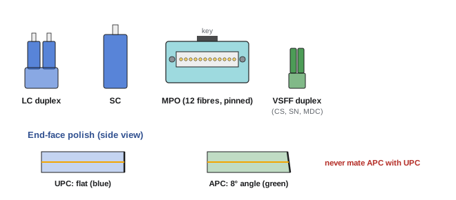
- LC: a small 1.25 mm ferrule duplex connector, the standard for two-fiber (duplex) links and for breakout of parallel optics. LC replaced the larger SC connector in most data center uses, although SC remains common in carrier and outside plant equipment.
- MPO (multi-fiber push-on): a rectangular ferrule holding 8, 12, 16 or 24 fibers in rows, used for parallel optics and for trunk cables. MTP is a widely used high-performance brand of MPO. Lesson 6 covers MPO polarity and design in detail.
- Very small form factor (VSFF) connectors such as CS, SN and MDC: duplex connectors much smaller than LC, which allow two or more independent connections in the space of one LC duplex port and fit the breakout ports of 400G and 800G transceivers.
Single-mode connectors also differ by end-face polish. UPC (ultra physical contact) connectors have a domed, flat-to-the-axis end face, usually blue. APC (angled physical contact) connectors are polished at 8°, so any light reflected at the joint is sent into the cladding rather than back toward the laser; they are green and are required by many single-mode optics, including MPO-based DR4. An APC connector must never be mated with a UPC connector: the angled and flat faces meet with an air gap, causing high loss and possible end-face damage.
Total cost of a link
The cable itself is usually a small part of a link's cost. A full comparison includes:
- Transceivers at both ends, which for high-speed links often cost several times the cabling.
- Connectors, panels, cassettes and installation labor, including termination and testing.
- Power: transceivers and copper PHYs draw power continuously, and every watt also costs cooling. 10GBASE-T ports draw several watts each, compared with roughly 1 W for a 10 Gb/s short-reach optic.
- Lifetime: a structured plant should last through several generations of network equipment (often 10 to 15 years), while transceivers are replaced with each generation.
Worked problem
Comparing two options over a lifetime
A designer compares two plants for 1000 links of 100 m or less. Option M: OM4 multimode, installed cost $900 per link, with 100G-SR4 optics at $150 each. Option S: single-mode, installed cost $1000 per link, with 100G-DR optics at $200 each. Each link needs two optics. The plant will see three generations of optics. If optic prices hold (in reality both fall), what is the cost of each over the plant's life?
Show solution
- Option M: cabling 1000 × 900 = $900,000; optics 1000 × 2 × 150 × 3 generations = $900,000. Total $1.80 M.
- Option S: cabling 1000 × 1000 = $1,000,000; optics 1000 × 2 × 200 × 3 = $1,200,000. Total $2.20 M.
- But option M can only carry interfaces with multimode versions at 100 m or less. If the third generation of optics has no multimode version at the needed reach, the hall must be re-cabled with single-mode: about $1.0 M more, plus disruption.
Answer: Multimode is $0.4 M cheaper if all three generations can use it, but $0.6 M more expensive if it must be replaced for the third. The decision rests on the operator's view of future optics, which is why many new facilities choose single-mode even where multimode is cheaper today.
The following lessons go deeper into each medium: Lesson 3 covers copper channel performance and PoE, Lesson 4 the physics of loss, dispersion and wavelengths in fiber, and Lesson 5 the transceivers and breakouts that decide what each link must carry.
Common mistakes
MistakeChoosing media by cable price alone.
InsteadCompare the whole channel over its life: optics, power, installation and the cost of re-cabling for future speeds.
MistakeAssuming faster multimode optics reach further than older ones.
InsteadMultimode reach has stayed near 100 m on OM4 as speeds rose, and is shorter on OM3.
MistakeMating APC and UPC connectors.
InsteadAPC (green) mates only with APC; UPC (blue) only with UPC. Mixing them causes high loss and can damage end faces.
MistakeMixing OM3, OM4 and OS2 patch cords in one plant without identification.
InsteadUse the standard jacket colors and labels, and never mix multimode and single-mode in one channel.
MistakeIncluding DAC and AOC cables in the structured cabling count.
InsteadThey are equipment cords bought with the network gear; plan pathways for them but not panel ports.
Summary and key terms
- Media choice depends on length, speed, the optics available, total lifetime cost, power and future upgrades.
- Category 6A is the minimum for new horizontal copper (10 Gb/s to 100 m); Category 8 reaches 30 m at 25/40 Gb/s.
- DAC, AEC and AOC cables serve the shortest links and are equipment cords, not structured cabling.
- Fiber guides light in a core by total internal reflection; attenuation and dispersion limit reach.
- Multimode (50 µm, OM3/OM4/OM5) uses low-cost VCSELs but reaches about 100 m at high speed; single-mode (9 µm, OS2) reaches kilometers.
- Single-mode parallel optics (DR4, DR8) have made single-mode the default in hyperscale and AI facilities.
- Connectors: LC duplex, MPO multi-fiber, VSFF (CS, SN, MDC); APC and UPC polishes must not be mixed.
- The cabling plant should outlast several generations of transceivers.
- Balanced transmission
- Sending a signal as the difference between two conductors so that common interference cancels.
- Category 6A
- Twisted-pair cabling tested to 500 MHz, supporting 10GBASE-T to 100 m.
- Direct-attach copper (DAC)
- A twinaxial cable with transceiver plugs on both ends for very short links.
- Active optical cable (AOC)
- A cable with optical transceivers built into its plugs and fiber between them.
- Multimode fiber
- Fiber with a 50 µm core that carries many modes of light.
- Single-mode fiber
- Fiber with a core of about 9 µm that carries one mode, for long reach.
- Attenuation
- Loss of optical power along a fiber, in dB/km.
- Modal dispersion
- Pulse spreading caused by light traveling along paths of different length in multimode fiber.
- Effective modal bandwidth (EMB)
- A measure of multimode fiber bandwidth in MHz·km.
- VCSEL
- Vertical-cavity surface-emitting laser: a low-cost laser used with multimode fiber.
- Bend-insensitive fiber
- Fiber designed to lose little light in tight bends (G.657 for single-mode).
- LC connector
- A small-form-factor connector with a 1.25 mm ferrule, usually used in duplex pairs.
- APC
- Angled physical contact: an 8° polished end face that reduces back reflection.
- VSFF connector
- Very small form factor duplex connectors such as CS, SN and MDC.
Practice problems
Work each problem on paper first, then reveal the answer to check.
What is the maximum reach of 100GBASE-SR4 on OM3 and on OM4?
Show answer
70 m on OM3 and 100 m on OM4.
A 120 m link must carry 400 Gb/s. Which media and optic would you use?
Show answer
Single-mode fiber with 400GBASE-DR4 (500 m) or FR4 (2 km); multimode SR8 reaches only 100 m on OM4.
Why has multimode reach not increased with speed?
Show answer
Higher signaling rates tolerate less modal dispersion, so reach stays near 100 m and speed is increased with more lanes or wavelengths instead.
Calculate the attenuation of 2 km of single-mode fiber at 1310 nm using the typical OS2 figure and the TIA-568.3 inside plant maximum.
Show answer
Typical: 2 × 0.4 = 0.8 dB. Inside plant maximum: 2 × 1.0 = 2.0 dB.
What jacket colors identify OM4, OM5 and OS2 cable?
Show answer
OM4 aqua (or violet), OM5 lime green, OS2 yellow.
Why must shielded twisted-pair cabling be bonded?
Show answer
An unbonded shield can act as an antenna and carry interference or fault voltages; bonding at the panel to the TIA-607 system drains them.
A 10GBASE-T port draws 4 W and a 10G SR optic 1 W. For 2000 links (two ends each), what is the difference in power, and in annual energy at a PUE of 1.4?
Show answer
2000 × 2 × 3 W = 12 kW; × 1.4 = 16.8 kW at the facility; × 8760 h ≈ 147,000 kWh per year.
What happens if an APC connector is mated with a UPC connector?
Show answer
The angled and flat end faces leave an air gap, causing high insertion loss and reflection, and the end faces can be damaged.
Give two reasons a designer might still choose OM4 multimode for a new enterprise hall.
Show answer
Lower-cost multimode optics and existing spares and skills; all links are under 100 m and equipment refreshes are expected to keep multimode options.
Which link types normally use DAC, and why are they excluded from the structured plant?
Show answer
Server-to-ToR and other in-cabinet or adjacent-cabinet links of a few meters; they are fixed-length equipment cords replaced with the network equipment.
Lesson quiz · 5 questions
Score 60% or more to complete this lesson.
Create a free account to save your progress, take quizzes and earn a certificate.