
BLR-330 · Lesson 9 of 12 · 20 min
Damage mechanisms and what inspectors look for
On the sixth day Ruth Ambrose, Northgate's fixed equipment engineer, sits down with Teodor and Kiera at a table in the inspection trailer covered in thickness readings from V-2204. The shell has been thinning faster since 2023 than before, and Ruth wants to know why. "Every piece of equipment in this plant is being damaged by something," she says. "Our job is to know what, how fast and where, so we inspect in the right places with the right tools and fix things before they fail." She explains that in 2023 the unit started running a crude with more sulfur and chlorides, and the overhead system has seen more water and acid since. This lesson explains how equipment is damaged in service, the main damage mechanisms boilermakers will meet, how inspectors find them and how corrosion rates and remaining life set the next inspection.
Damage mechanisms
A damage mechanism is a particular way that equipment deteriorates in service: a kind of corrosion, cracking, metallurgical change or mechanical damage, each with its own causes, its own appearance and its own inspection methods. The refining industry's main reference is API RP 571, Damage Mechanisms Affecting Fixed Equipment in the Refining Industry, whose third edition was published in 2020. It describes more than sixty mechanisms, the materials and conditions in which each occurs, what the damage looks like, how to inspect for it and how to prevent it. Other industries use similar references.
Knowing the mechanism matters because inspection methods find some kinds of damage and miss others. A thickness gauge finds general thinning but misses fine cracks. Magnetic particle testing finds surface cracks in steel but not thinning. Some damage, such as high temperature hydrogen attack, is hard to find with any method and must be prevented by staying within safe operating limits. An inspection plan that does not start from the damage mechanisms may look thorough and still miss the thing that causes a failure.
| Family | Examples | What it looks like |
|---|---|---|
| General and local thinning | Sulfidation, acid corrosion, erosion, flow-accelerated corrosion | Wall loss, grooves, pits |
| Environmental cracking | Wet hydrogen sulfide damage, chloride stress corrosion cracking, caustic cracking | Fine cracks, blisters |
| High temperature damage | Creep, high temperature hydrogen attack, overheating | Bulging, distortion, internal fissures |
| Mechanical damage | Thermal fatigue, vibration fatigue, mechanical wear | Cracks at welds and attachments, worn surfaces |
| External damage | Corrosion under insulation, atmospheric corrosion | Rust and wall loss hidden under insulation |
Thinning mechanisms
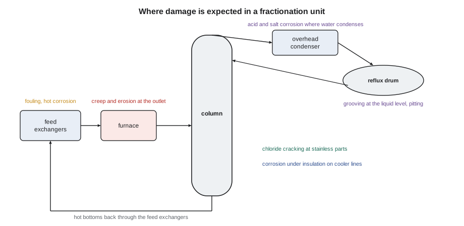
Thinning is the commonest damage in process plants. General corrosion removes metal over a large area at a fairly even rate, which a thickness survey tracks well. Local corrosion is concentrated: pitting, grooving at a liquid level, attack at welds or under deposits. Erosion and erosion-corrosion remove metal where flow is fast or turbulent, at inlets, elbows and impingement points. In refineries, sulfidation attacks carbon and low-alloy steels at high temperature where sulfur compounds are present; naphthenic acid corrosion attacks hot equipment in crude units; and acid corrosion from hydrochloric acid, ammonium salts and sour water attacks overhead systems where water condenses.
Overhead drums like V-2204 are classic places for aqueous corrosion. As the column overhead cools, water condenses with hydrogen chloride and hydrogen sulfide dissolved in it, forming acids that attack carbon steel. Ammonium chloride and ammonium bisulfide salts can deposit and corrode under the deposits. The rate depends on the crude, the wash water, the neutralizer and the temperatures, all of which operations control. When the crude changed in 2023, the overhead conditions changed with it.
Cracking mechanisms
Cracking is more dangerous than thinning because cracks can grow quickly and fail with little warning, and because they are harder to find. In wet hydrogen sulfide service, atomic hydrogen from corrosion enters the steel and causes blistering, hydrogen-induced cracking and stress-oriented cracking, especially at hard welds; vessels in this service are often made of resistant steel and their welds are kept soft. Chloride stress corrosion cracking attacks austenitic stainless steels in hot, wet chloride environments, often under insulation. Caustic cracking attacks carbon steel in hot caustic service, at welds that were not stress relieved. Amine cracking and carbonate cracking occur in gas treating units.
Mechanical and thermal fatigue cause cracking where loads or temperatures cycle. Delayed coker drums, like the ones Ironbridge set in an earlier course, are heated and cooled every day or two, and the repeated cycles cause bulging of the shell and cracking at the welds and the skirt attachment. That is why the D-1 skirt crack is on the work list: Northgate monitors it at every turnaround, and the engineer decides whether it can run another cycle or must be repaired.
High temperature and external damage
Equipment that runs hot faces creep, the slow stretching of metal under stress at high temperature, which shows as bulging and finally rupture of furnace tubes and boiler superheater tubes. Overheating, from flame impingement or deposits, speeds up creep and can cause short-term ruptures. High temperature hydrogen attack occurs in hot hydrogen service, where hydrogen reacts with carbon in the steel and forms methane inside it, weakening the steel from the inside. It is guided by API RP 941, which gives safe operating limits for each steel, and it is managed mainly by keeping equipment within those limits, because inspection for it is difficult.
Corrosion under insulation, often called CUI, attacks the outside of insulated equipment and piping when water gets under damaged insulation and cannot dry out. It is worst on carbon steel running between about freezing and the temperature at which water boils off quickly, and on stainless steels it can cause chloride cracking. Because the damage is hidden, it is found only by removing insulation, by special inspection methods or by a leak. Many owners have large CUI programs that run between turnarounds, which is why the insulation repair on line 8-P-2215 was moved out of the turnaround scope rather than ignored.
How inspectors find damage
Inspectors choose methods to suit the expected damage. Visual inspection is always first. Ultrasonic thickness measurement tracks thinning. Magnetic particle and liquid penetrant testing find surface cracks. Ultrasonic shear wave, phased array and time-of-flight diffraction methods find and size cracks inside the metal and are used for wet hydrogen sulfide damage and fatigue cracks. Radiography shows thinning and pitting in piping. Eddy current and other electromagnetic methods test exchanger tubes. Hardness testing checks welds for susceptibility to cracking. Metallurgical replicas and samples show creep and other changes in the structure of the metal.
The inspection plan for each piece of equipment lists its damage mechanisms, the methods and coverage to look for each, and the interval. In the United States and Canada, owners often use risk-based inspection, which ranks equipment by the likelihood and consequence of failure and sets intervals and methods accordingly. The inspection codes allow this, within limits. Whatever system is used, the boilermaker's part is the same: give the inspector access and clean surfaces, and report anything unusual seen during the work.
| Method | Finds | Misses |
|---|---|---|
| Visual | Gross damage, leaks, distortion, deposits | Hidden or fine damage |
| Ultrasonic thickness | General and local thinning at the points measured | Cracks; thinning between points |
| Magnetic particle | Surface and near-surface cracks in steel | Thinning; deep internal flaws |
| Penetrant | Surface cracks in any non-porous metal | Subsurface flaws |
| Shear wave and phased array ultrasonics | Internal cracks, with size and depth | Very small flaws in coarse metals |
| Eddy current | Wall loss and cracks in non-magnetic tubes | Carbon steel tubes without special methods |
Corrosion rates and remaining life
For thinning, inspectors calculate a corrosion rate from repeated thickness readings at the same locations. Under API 510, the inspection code for pressure vessels in service, whose eleventh edition was published in 2022, two rates are compared. The long-term rate is the loss from the first reading to the latest divided by the years between them. The short-term rate is the loss between the last two readings divided by the years between them. The inspector, with a corrosion specialist where needed, decides which rate best reflects current conditions; if the short-term rate is higher, it usually means conditions have changed, and it governs.
The remaining life is the thickness left above the required thickness, divided by the corrosion rate. The required thickness comes from the design calculation for the vessel's pressure and temperature, without any corrosion allowance. API 510 sets the interval for the next internal or on-stream inspection as the lesser of half the remaining life and ten years, and the interval for external visual inspection as the lesser of five years and the internal interval. Similar rules apply to piping under API 570 and to storage tanks under API 653.
Worked problem
Remaining life of V-2204
V-2204's shell was 0.750 in thick when first measured in 1998. In 2023 it read 0.665 in, and this turnaround it reads 0.594 in at the worst monitoring location. The required thickness is 0.488 in. Find the long-term and short-term rates, the remaining life and when the next internal inspection is due.
Show solution
- Long-term rate: (first reading minus latest) divided by 31 years.
- Short-term rate: (2023 reading minus latest) divided by 6 years.
- Use the higher rate, because conditions have changed.
- Remaining life is the wall above the required thickness divided by the rate; the interval is the lesser of half of it and 10 years.
Answer: The short-term rate is more than twice the long-term rate. The remaining life is 9.0 years, so the next internal inspection is due within 4.5 years, by about April 2034.
# Remaining life and next inspection date for a vessel shell (API 510 approach)
from datetime import date
T_INITIAL = 0.750       # first thickness reading (in), taken in 1998
T_PREV = 0.665          # previous reading (in), taken in 2023
T_ACTUAL = 0.594        # this turnaround's reading (in), 2029
T_REQ = 0.488           # required thickness from the design calculation (in)
long_rate = (T_INITIAL - T_ACTUAL) / (2029 - 1998)
short_rate = (T_PREV - T_ACTUAL) / (2029 - 2023)
rate = max(long_rate, short_rate)          # use the more severe rate unless the inspector justifies otherwise
life = (T_ACTUAL - T_REQ) / rate
interval = min(life / 2, 10)
print(f"Long-term rate {long_rate:.4f} in/yr, short-term rate {short_rate:.4f} in/yr; using {rate:.4f}")
print(f"Remaining life = ({T_ACTUAL} - {T_REQ}) / {rate:.4f} = {life:.1f} years")
print(f"Next internal inspection within {interval:.1f} years (the lesser of half the remaining life and 10 years)")
months = round(interval * 12)
y, m = divmod(10 - 1 + months, 12)
due = date(2029 + y, m + 1, 1)
print(f"Due by about {due:%B %Y}; external visual inspection at least every {min(5, interval):.1f} years")Long-term rate 0.0050 in/yr, short-term rate 0.0118 in/yr; using 0.0118 Remaining life = (0.594 - 0.488) / 0.0118 = 9.0 years Next internal inspection within 4.5 years (the lesser of half the remaining life and 10 years) Due by about April 2034; external visual inspection at least every 4.5 years
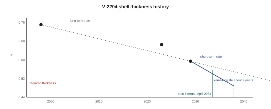
The result changes the plan for V-2204. The vessel is fit for service, but at the new rate it would reach its required thickness in about nine years, well before the old plan expected. Ruth and Teodor recommend three things: the next internal inspection in four and a half years instead of ten, on-stream ultrasonic checks every year at the worst locations, and a review of the overhead wash water and neutralizer with operations to bring the rate down. In the longer term, a replacement drum with a corrosion-resistant lining may be planned for the following turnaround. The work is recorded in the inspection report and the vessel's file.
Kiera's crew will not do the calculation on a job, but they will see its results: the condition monitoring locations they must leave accessible, the repairs and replacements that come from it and the dates on the inspection plan. Understanding the reasons, Ruth tells her, is what lets a boilermaker spot the thing that does not fit, such as a deposit in the wrong place or a crack where none was expected, and report it.
Common mistakes
MistakeAssuming one inspection method finds all damage.
InsteadChoose methods for the expected damage mechanisms; thickness gauges miss cracks.
MistakeUsing the long-term corrosion rate when conditions have changed.
InsteadCompare long-term and short-term rates; a higher short-term rate usually governs.
MistakeIncluding the corrosion allowance in the required thickness.
InsteadThe required thickness is for pressure only; the allowance is the metal available to corrode.
MistakeIgnoring insulated lines because they look fine.
InsteadCorrosion under insulation is hidden; it is found only by looking under the insulation or with special methods.
Summary and key terms
- A damage mechanism is a particular way equipment deteriorates; API RP 571 (3rd edition, 2020) describes them for refining.
- Thinning, cracking, high temperature damage, mechanical damage and external damage each need their own inspection methods.
- Overhead systems suffer acid and salt corrosion; coker drums suffer thermal fatigue; hot hydrogen equipment is guided by API RP 941.
- Inspection plans list damage mechanisms, methods, coverage and intervals; many owners use risk-based inspection.
- API 510 compares long-term and short-term corrosion rates; remaining life is the wall above required divided by the rate.
- The next internal inspection is due within the lesser of half the remaining life and 10 years.
- Damage mechanism
- A specific way equipment deteriorates in service.
- Long-term corrosion rate
- Wall loss from the first reading to the latest, divided by the years between them.
- Short-term corrosion rate
- Wall loss between the last two readings, divided by the years between them.
- Remaining life
- The time until the wall reaches the required thickness at the corrosion rate.
- Required thickness
- The minimum wall needed for the design pressure and temperature, without corrosion allowance.
- CUI
- Corrosion under insulation.
Practice problems
Work each problem on paper first, then reveal the answer to check.
Why is the short-term rate used for V-2204?
Show answer
It is higher than the long-term rate, showing that conditions changed after 2023.
A vessel has 20 years of remaining life. When is the next internal inspection due under API 510?
Show answer
Within 10 years, since half the remaining life is more than the 10-year maximum.
Which method would you expect for wet hydrogen sulfide cracking at a weld?
Show answer
Magnetic particle testing for surface cracks and shear wave or phased array ultrasonics for internal cracks.
Why was the CUI repair on line 8-P-2215 moved out of the turnaround?
Show answer
Insulation can be removed and the pipe inspected with the line in service, so it does not need the shutdown.
Lesson quiz · 5 questions
Score 60% or more to complete this lesson.
Create a free account to save your progress, take quizzes and earn a certificate.