
BAS-410 · Lesson 7 of 12 · 20 min
Test and balance coordination
▶ Video coming soon A video version of this lesson is on the way.
Brenna Fairweather of Stelmark Balancing arrived at Marlow Lane on Wednesday, October 14 with a flow hood, a pitot tube and manometer, a hydronic meter and a list of requests for Ivo. She needed AHU-1's fans at full speed, all the boxes on the second floor driven to maximum and then minimum, the outdoor air damper held at its minimum position, and the static pressure loop out of the way while she found the right setpoint. "Balancing is the one trade that cannot work without the controls," Ivo told Callie, "and the controls cannot be finished without balancing. You have to plan it together or you both waste days."
What TAB is
Testing, adjusting and balancing (TAB) measures the air and water flows in a system, adjusts dampers, valves and fan or pump speeds until the flows match the design, and records the results in a TAB report. The work is done by a specialist firm with calibrated instruments. Balancing standards are published by the bodies that certify TAB firms and technicians, such as the Associated Air Balance Council (AABC) and NEBB; TABB is another certification used in the US. Specifications usually require a certified firm and name the standard to be followed.
In the US, AABC, NEBB and TABB all certify firms, and specifications often name one or accept any of them. Where the IECC's commissioning section applies, it also requires air and hydronic systems to be balanced and the balancing report to be available.
TAB is part of the construction phase and comes after the pre-functional checklists and point-to-point checkout of the systems being balanced, and before their functional tests. If the controls are not ready, the balancer cannot drive the equipment where it needs to be. If balancing is not done, the functional tests measure airflows that have not been set or calibrated.
What TAB needs from the controls
A balancer needs to put each system into a known condition and hold it there while measuring. With a BAS, that means overriding outputs and setpoints, and on VAV systems it means driving boxes to their maximum and minimum airflows one at a time or a floor at a time.
| TAB needs | What the controls contractor provides |
|---|---|
| Fans at design speed, then held at other speeds | Drive speed overrides on AHU-1's supply and return fans, released after each measurement |
| Outdoor air damper at minimum position | Economizer held at minimum; mixed air low limit left active |
| VAV boxes at maximum and minimum airflow | A front-end command or a tool to drive each box, or each floor, to maximum or minimum |
| Box airflow readings to compare with the hood | The box's airflow reading on the screen next to the hood reading, and the ability to change the airflow factor |
| Static pressure loop out of the way | Static pressure setpoint changeable, or the supply fan speed held |
| Pumps at design speed, valves fully open | Pump speed and valve overrides; a list of which coil valves are open |
| Someone to answer questions | A controls technician on site or on call for the whole TAB period |
On Marlow Lane, Ivo set up a front-end account for Brenna with access to a commissioning page that Sophie had built: one table per floor with each box's airflow setpoint, airflow reading, damper position and buttons to command maximum, minimum or automatic. Brenna could stand at a diffuser with the flow hood, set the box to maximum from a tablet, read the hood, and compare it with the box's own reading on the same screen. The account was removed at the end of balancing, as BAS-320 recommended for contractor accounts.
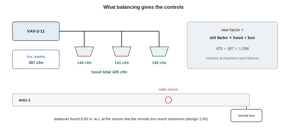
What the controls need from TAB
Balancing does not just set flows; it gives the controls several of their final settings. Without them, the controls run on design guesses.
- Calibrated airflow readings. Each VAV box measures airflow with a pickup and a pressure transducer, converted to flow with a factor (often called a K-factor or flow coefficient) from the box maker. The balancer measures the real flow with a hood or a traverse, and the factor is adjusted so the box reading matches.
- The duct static pressure setpoint. The balancer finds the static pressure at the sensor that lets the hardest-to-supply box reach its design airflow. That becomes the maximum of the static pressure reset.
- The minimum outdoor air setting. The balancer measures outdoor airflow at minimum and sets or verifies the damper position or the airflow station reading that delivers the design minimum.
- Pump and coil settings. The balancer sets hydronic flows and often the pump differential pressure setpoint.
Calibrating box airflow
Brenna measured each box at maximum and at minimum. At maximum, the hood total and the box reading usually differ a little, because the factor from the maker assumes ideal inlet conditions and real ductwork is never ideal.
Worked problem
Correcting an airflow factor
VAV-2-11 has a cooling maximum of 425 cfm. With the box at maximum, its own reading was 387 cfm while the hood total across its three diffusers was 425 cfm. Airflow is calculated as the factor times the square root of the velocity pressure, so the reading changes in proportion to the factor. By how much should the factor be changed?
Show solution
- Correction ratio: hood ÷ box reading = 425 ÷ 387 = 1.098.
- New factor = old factor × 1.098.
- Recheck: with the new factor, the box reading at the same velocity pressure becomes 387 × 1.098 = 425 cfm.
Answer: Increase the factor by about 10 in 100. Before the correction, the box was delivering design flow while believing it was 9 in 100 low, so in operation it would have driven itself about 10 in 100 above its setpoint. Ivo entered the new factor, Brenna rechecked the maximum, and both recorded the before and after values.
At minimum, a box's pressure signal is small and the reading less accurate, so the balancer checks it separately. VAV-2-11's minimum was 125 cfm on the design schedule; the hood read 119 cfm, about 5 in 100 low. TAB tolerances are commonly about 10 in 100 at terminals (typical; the specification governs), so it passed. Where a minimum is badly out with a correct maximum, the cause is often the transducer's zero or a leaky damper, not the factor, and changing the factor would spoil the maximum.
One balancing figure that VAV-2-11 shows clearly: the minimum flow for a box is set by ventilation and heating needs, not by what the controller can measure comfortably. If the minimum is so low that the velocity pressure is below what the transducer can read reliably, the box will control badly. That was a design review topic on Marlow Lane, and none of the minimums fell below the transducers' range.
Total airflow and the static pressure setpoint
With all boxes at maximum, which approximates the design condition, Brenna measured AHU-1's total supply airflow by a pitot traverse in the supply duct.
Worked problem
Is the total airflow in tolerance?
AHU-1's design supply airflow is 19,900 cfm, and the traverse measured 20,650 cfm with the supply fan at the speed that brought the last box to its maximum. The specification asks for total fan airflow between 0 and 10 in 100 above design (a common tolerance). Is it in tolerance?
Show solution
- Ratio: 20,650 ÷ 19,900 = 1.038.
- That is about 3.8 in 100 above design, within 0 to 10 in 100.
Answer: In tolerance. The total is slightly higher than design because each box was set to its own maximum and the duct system leaks a little; the box readings, now calibrated, are what the controls will use in operation.
Next, Brenna found the static pressure setpoint. With all boxes at maximum, she lowered the static pressure setpoint until the most remote box on the third floor could just hold its maximum with its damper fully open, then added a small margin. The result was 0.85 in. w.c. at the sensor, lower than the 1.00 in. w.c. design value in the sequence. Ivo set the reset's maximum to 0.85 in. w.c. and kept its minimum at 0.40 in. w.c. The burn-in trends (lesson 6) later showed the reset moving between those limits as boxes called for air.
That one change is worth money every hour the fan runs, because fan power falls steeply with pressure. It is also an example of TAB improving on the design: the design value was a reasonable estimate before the ducts existed; the balanced value is a measurement.
Minimum outdoor air
The design minimum outdoor air for AHU-1 is 4,030 cfm. The new controls included an outdoor airflow measuring station in the minimum outdoor air duct, so the controls could hold the minimum at any fan speed rather than relying on a fixed damper position (the problem BAS-230 found at Tilden, where the minimum position delivered the design minimum only at full speed). Brenna traversed the duct and measured 4,070 cfm while the station read 3,920 cfm, about 3.7 in 100 low. Airflow stations are often specified to about 5 in 100 (typical), so it passed, and Ivo applied a small correction so the station matched the traverse.
Coordinating the schedule
Balancing at Marlow Lane took five working days, from October 14 to October 20, for AHU-1, 30 of the 36 boxes, the exhaust fans and the hot water system. The other six boxes, in a first-floor suite where the tenant's contractor was still finishing a ceiling, could not be balanced until Friday, October 30, during the burn-in week. That is why the burn-in alarm list shows 52 airflow alarms from six boxes with their factors not yet set (lesson 6), and why those six boxes were left out of the October 22 functional test sample and tested on their own on Monday, November 2, after their factors had been entered. All six passed.
Ivo's coordination checklist for TAB, which Quillon now uses on its own jobs:
- Before TAB starts: checkout complete on the systems to be balanced; commissioning page or tool ready; contractor account set up; a list of the overrides TAB will need.
- During TAB: a controls technician on site or on call; every override logged and released; airflow factors and setpoints changed only together with the balancer, with before and after values recorded.
- After TAB: the TAB report's settings (factors, static pressure maximum, minimum outdoor air correction, pump settings) entered in the controls and listed in the as-built documents; the contractor account removed; a backup taken.
The TAB report and its review
The TAB report lists every measured flow against design, every setting made, the instruments used and their calibration. The commissioning provider reviews it and usually verifies a sample of its readings on site, with the balancer present. Philippa re-measured AHU-1's total airflow and four boxes with Brenna, a sample chosen from the report on the day. All five readings were within 10 in 100 of the report's values, which her plan set as the threshold; if more than one had been out, she could have rejected the report and asked for the work to be repeated.
Balancing raised five issues of its own on Marlow Lane: two third-floor diffusers with their dampers closed by the ceiling contractor; a hot water coil on box VAV-3-10 with its balancing valve closed; AHU-1's return fan tracking set so that the building ran slightly negative, corrected with the static pressure readings; VAV-1-02's heating airflow (the corner office in lesson 6), which met its design value but looked small for the room; and a missing test port on the hot water supply. All went into the issues log.
Hydronic balancing and the controls
Balancing covers water as well as air. On Marlow Lane, Brenna measured the flow through each boiler and through the AHU-1 heating coil with her hydronic meter at the balancing valves, set the coil's balancing valve, and checked the pump's speed at design flow. She also found the issue at VAV-3-10: its coil's balancing valve was closed, so the box's reheat valve could open fully and the room would still not heat. On a VAV floor, that kind of fault looks like a controls problem from the front end, because the valve command and position look normal while the discharge air temperature does not rise.
Pump control is where hydronic balancing and controls meet most directly. If the pump runs on a differential pressure setpoint, the balancer finds the setpoint that delivers design flow to the hardest coil, in the same way as the static pressure setpoint for air. Marlow Lane's heating pumps run at a fixed speed set by the balancer, with two-way valves, so the controls job was to record that speed and alarm if a pump was not running. The record goes into the sequence as built, so that nobody later changes the speed without rebalancing.
The balancer's instruments matter as much as the controls technician's. A TAB report lists each instrument with its calibration date, and the commissioning provider checks that the dates are current. The same rule applies to the reference thermometer and manometer on the checkout sheets: a reading taken with an uncalibrated instrument proves nothing, however carefully it was recorded.
Common mistakes
MistakeStarting TAB before the controls can drive the equipment.
InsteadFinish checkout and set up the tools the balancer needs first, or the balancer's days are wasted.
MistakeChanging airflow factors without the balancer.
InsteadFactors should only change against a measured flow, with before and after values recorded together.
MistakeLeaving the design static pressure setpoint after balancing.
InsteadUse the setpoint the balancer found; it is a measurement rather than an estimate, and usually saves fan energy.
MistakeFixing a bad minimum reading by changing the factor.
InsteadCheck the transducer zero and the damper first; changing the factor to fix the minimum spoils the maximum.
Summary and key terms
- TAB measures and sets air and water flows and records them in a report; certified firms follow standards from bodies such as AABC and NEBB.
- The controls must let the balancer drive fans, dampers, boxes and pumps to known conditions.
- TAB gives the controls their calibrated airflow factors, static pressure setpoint, minimum outdoor air correction and pump settings.
- Factors are corrected by the ratio of the measured flow to the box reading, at maximum.
- The commissioning provider reviews the TAB report and verifies a sample of readings on site.
- Testing, adjusting and balancing (TAB)
- Measuring and adjusting air and water flows to design values, with a report of the results.
- Airflow factor
- The coefficient that converts a VAV box's measured velocity pressure into airflow; also called a K-factor or flow coefficient.
- Traverse
- A set of velocity readings across a duct used to calculate the total airflow.
- Flow hood
- An instrument placed over a diffuser or grille to measure its airflow directly.
- Airflow measuring station
- A permanent device in a duct that measures airflow, such as minimum outdoor air.
Practice problems
Work each problem on paper first, then reveal the answer to check.
A box reads 320 cfm at maximum while the hood reads 352 cfm. What correction ratio should be applied to its factor?
Show answer
352 ÷ 320 = 1.10, so increase the factor by 10 in 100 and recheck.
Why was the static pressure maximum set to 0.85 in. w.c. instead of 1.00 in. w.c.?
Show answer
The balancer measured that 0.85 in. w.c. at the sensor let the most remote box reach its maximum; the higher design value would only waste fan energy.
Lesson quiz · 5 questions
Score 60% or more to complete this lesson.
Create a free account to save your progress, take quizzes and earn a certificate.