
BAS-110 · Lesson 9 of 12 · 24 min
Pumps, fans and variable frequency drives
▶ Video coming soon A video version of this lesson is on the way.
On Tuesday, October 27, Prakash and Callie spent the morning in Ninefield Tower's penthouse and basement looking at the motors that moved the building's air and water. The four penthouse air handlers had 20 hp supply fans on variable frequency drives. In the basement, the two secondary chilled water pumps had drives too, installed in 2008. The primary pumps and the condenser water pumps ran at constant speed. Prakash opened the cover of one drive's keypad, showed Callie the running frequency, the motor current and the fault history, and said, "Drives are where most of the electrical energy in this building goes. If you understand what a drive does to a fan or a pump, you will understand where the savings are."
This lesson explains how pumps and fans work, how they interact with the systems they serve, how their speed affects flow, pressure and power, and how variable frequency drives control them. It also covers the practical side: what a controls technician reads from a drive, what can go wrong and how to work around drives and motors safely.
Fans and pumps
Fans move air and pumps move water, but they work in much the same way. Most HVAC fans and pumps are centrifugal: a spinning impeller or wheel throws the fluid outward, raising its pressure, and a housing or volute collects it and sends it on. Axial fans, which push air along the shaft like a propeller, are used for exhaust, cooling towers and some large supply fans. Pumps in HVAC systems are usually end-suction or split-case centrifugal pumps, or in-line pumps mounted directly in the pipe. Each fan or pump has a performance curve, published by its maker, that shows how much flow it delivers against how much pressure at a given speed.
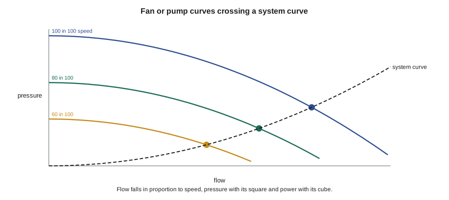
The system it serves has a curve too. Pushing air through ducts, filters and coils, or water through pipes, valves and coils, takes pressure, and the pressure needed rises with the square of the flow: twice the flow needs about four times the pressure. Where the fan or pump curve crosses the system curve is the operating point, the flow and pressure the equipment actually delivers. When a VAV box closes or a coil valve throttles, the system curve gets steeper and the operating point moves. When the fan or pump speed changes, its curve moves. Controls work by moving one or both.
The affinity laws
For a given fan or pump in a given system, three relationships, called the fan laws or affinity laws, connect speed to performance. Flow is proportional to speed: run the fan at 80 in 100 of its speed and it delivers about 80 in 100 of its flow. Pressure is proportional to the square of the speed: at 80 in 100 speed it develops about 64 in 100 of the pressure. Power is proportional to the cube of the speed: at 80 in 100 speed it needs only about 51 in 100 of the power. The cube law is why variable speed saves so much energy. A small reduction in speed gives a large reduction in power.
Worked problem
Fan power at reduced speed
One of Ninefield's AHU supply fans draws 15 kW at full speed. Assuming the affinity laws hold, what does it draw at 80 in 100 and at 60 in 100 of full speed? If the fan runs 4,000 hours a year at 80 in 100 speed instead of at full speed with dampers throttling the flow, about how much energy is saved?
Show solution
- At 80 in 100 speed: 15 × 0.8³ = 15 × 0.512 = 7.68 kW.
- At 60 in 100 speed: 15 × 0.6³ = 15 × 0.216 = 3.24 kW.
- Saving at 80 in 100 for 4,000 h, compared with full power: (15 − 7.68) × 4,000 = 29,280 kWh.
- In practice the saving is somewhat less, because a throttled fan at full speed also draws less than full power, and because motors and drives lose some efficiency at low loads.
Answer: About 7.7 kW at 80 in 100 speed and 3.2 kW at 60 in 100; on the order of 29,000 kWh a year in this simple comparison.
The affinity laws hold exactly only when the system curve passes through zero pressure at zero flow, which is roughly true for a duct system with no static pressure setpoint. Real VAV systems hold a minimum duct pressure, and real pumping systems hold a minimum differential pressure, so the pressure does not fall all the way with the flow and the savings are smaller than the cube law suggests. That is one reason static pressure reset and differential pressure reset, covered in lessons 3 and 6, matter so much: the lower the pressure setpoint, the closer the system gets to cube-law savings.
Worked problem
Pump head at reduced speed
A secondary chilled water pump develops 67 ft of head at full speed. What head does it develop at 80 in 100 speed, by the affinity laws?
Show solution
- Head scales with the square of speed: 67 × 0.8² = 67 × 0.64 = 42.9 ft.
Answer: About 43 ft of head. If the differential pressure setpoint at the far end of the loop needs more than that, the pump cannot slow down that far.
Ways to control flow
Before drives were cheap, flow was controlled mechanically. Fans used outlet dampers or inlet guide vanes, adjustable vanes at the fan inlet that pre-spun the air, and pumps used throttling valves or bypass valves. All of these reduce flow by adding resistance or by wasting the energy the fan or pump adds, so the motor still works nearly as hard. Some older fans used two-speed motors or variable-pitch blades. Today, variable frequency drives have replaced almost all of these methods in new work and in most retrofits, because they reduce the motor's speed and so save power by the cube law.
Variable frequency drives
A variable frequency drive, or VFD, controls the speed of an AC induction motor by changing the frequency and voltage of the power it supplies. A standard motor runs at a speed set by the supply frequency, 60 Hz in Canada and the United States, and the number of poles in its winding: a four-pole motor runs at a little under 1,800 rpm. The drive first converts the incoming AC power to DC, then switches that DC on and off very rapidly to build a new AC waveform at whatever frequency the motor should run. At 48 Hz the same motor runs at about 80 in 100 of its full speed.
The drive receives a speed command from the BAS, usually a 0 to 10 V or 4 to 20 mA analog output, or a value over BACnet or another network, and a start command, usually a binary output closing a contact. It returns its running status, its speed or frequency, its motor current and its fault status, either as hard-wired points or over the network. A drive on BACnet can provide dozens of points, including power, energy, run hours and the details of its last fault. The BAS must never be the only protection for the motor: the drive has its own overload, overcurrent, overvoltage and phase-loss protection, and hard-wired safeties such as freeze stats and high-pressure limits are usually wired into the drive's safety input so that they stop the motor even if the BAS fails.
| Signal | Direction | Typical form | Purpose |
|---|---|---|---|
| Start / stop | BAS to drive | Binary output (contact closure) | Runs or stops the motor |
| Speed command | BAS to drive | 0–10 V, 4–20 mA or network value | Sets the running speed |
| Run status | Drive to BAS | Binary input or network point | Proves the drive is running |
| Fault | Drive to BAS | Binary input or network point | Alarms a drive trip |
| Speed feedback | Drive to BAS | Analog input or network point | Shows actual speed |
| Safety interlock | Field device to drive | Hard-wired safety input | Stops the motor on freeze stat or high limit |
Most drives on critical equipment also have a bypass, a set of contactors that lets the motor run straight across the line at full speed if the drive fails. In bypass, the motor runs at full speed with no speed control, so dampers and valves must be able to handle the full flow and pressure. A fan running in bypass on a VAV system can over-pressurize ducts unless the high-pressure limit protects them. Some sites have redundant drives or simply a spare drive on the shelf instead of a bypass.
Drives and the electrical system
Drives have side effects that a controls technician should know about. Their rapid switching creates electrical noise, which can interfere with nearby sensor wiring unless control cables are routed away from motor leads and shielded where required. Their rectifiers draw current in pulses, creating harmonic currents that distort the building's voltage waveform and heat transformers and neutral conductors; large installations may need line reactors or harmonic filters. Long motor leads between a drive and its motor can cause voltage spikes that damage older motor insulation, so motors used with drives should be inverter-duty rated. And the switching can induce voltages on the motor shaft that discharge through the bearings, pitting them; shaft grounding rings are a common fix. These are mostly design and electrical concerns, but a technician who sees repeated bearing failures or erratic sensor readings near a drive should suspect them.
Drives also have minimum speeds. A fan or pump run too slowly may not move enough air or water to cool its motor, may let a chiller's flow drop below its minimum or may let air or water stratify. The drive's minimum frequency, often 15 to 20 Hz for fans and higher for pumps, is set during commissioning and should not be lowered without checking why it was set. Similarly, some fans have a resonant speed at which they vibrate badly, and drives can be programmed to skip it.
Pump arrangements and control
Pumps in HVAC systems are often installed in pairs, with one running and one on standby, or with both running at high load. The BAS alternates the lead pump on a schedule, such as weekly, so that both wear evenly and the standby is known to work, and starts the standby automatically if the lead fails to prove. Pump proof is usually a current switch or the drive's run status, sometimes backed up by a differential pressure switch across the pump. A pump that is running with its motor drawing current but moving no water, because a valve is closed or its coupling has failed, may still prove by current, so a differential pressure or flow proof is better on critical pumps.
Variable-speed pumps on systems with two-way valves are controlled to hold a differential pressure setpoint between the supply and return pipes, measured near the most remote load, as lesson 6 described for Ninefield's secondary pumps. When Callie looked at their trends, both pumps ran at almost exactly the same speed all day, about 52 Hz, whatever the load, because the differential pressure setpoint had been set high in 2008 and never reset. With most coil valves only partly open, the pumps were holding far more pressure than any coil needed. A reset of the setpoint based on valve position would let them slow down; Sophie added it to the list for the spring retro-commissioning.
Motors
Almost all fans and pumps in commercial buildings are driven by three-phase induction motors. Their nameplates give the rated power in kilowatts or horsepower, the voltage, the full-load current, the speed, the service factor and the efficiency class. Motor efficiency standards in Canada and the United States require premium-efficiency motors in most new equipment, and newer fans increasingly use electronically commutated (EC) motors, permanent-magnet motors with built-in electronics that control their own speed from a 0 to 10 V signal. EC motors are common in fan arrays, fan coils, fan-powered boxes and small air handlers.
A motor's current tells a lot about its load. A fan motor drawing much less current than usual may have a broken belt or a closed damper; one drawing more than usual may have a damper stuck open or a failing bearing. Trending motor current or drive power is one of the cheapest ways to watch equipment health. Lesson 10 shows how motor current, voltage and power are related.
Working safely on drives and motors
Drives and motors are line-voltage equipment, and work on their power wiring is for licensed electricians under the state and local rules. A controls technician lands control wiring on the drive's low-voltage terminals and programs its parameters through the keypad or the network, but must still treat a drive as dangerous. Drives contain large capacitors that hold a lethal charge for several minutes after power is removed; the drive's label gives the waiting time, and the DC bus voltage must be checked before any cover is opened. NFPA 70E sets out the electrical safe work practices most employers follow. A motor commanded off by the drive is not locked out: the BAS, a schedule, the keypad or the bypass can start it. Lockout means opening and locking the disconnect ahead of the drive, verifying that the motor cannot start and, for a fan, also blocking the wheel, which can windmill from airflow driven by another fan.
Common mistakes
MistakeAssuming the cube law gives the full saving on a system with a high pressure setpoint.
InsteadReset pressure setpoints downward so the system can approach cube-law savings.
MistakeLowering a drive's minimum speed to save more energy.
InsteadFind out why the minimum was set; motors, chillers and coils have flow limits.
MistakeRelying on current proof for a pump that could run dry or dead-headed.
InsteadUse differential pressure or flow proof on critical pumps.
MistakeRunning a fan in bypass without checking the duct high limit.
InsteadMake sure the high-pressure limit can stop it, because bypass runs at full speed.
MistakeOpening a drive cover as soon as power is off.
InsteadWait the labeled time and verify the DC bus voltage is safe.
MistakeTreating a drive's stop command as a lockout.
InsteadLock out the disconnect ahead of the drive, and block fan wheels.
Summary and key terms
- Fans and pumps operate where their performance curve crosses the system curve.
- System pressure rises with the square of flow.
- Affinity laws: flow ∝ speed, pressure ∝ speed², power ∝ speed³.
- Pressure setpoints limit how far real systems get toward cube-law savings, so reset them.
- A VFD changes motor speed by changing frequency and voltage; at 48 Hz a motor runs at about 80 in 100 speed.
- The BAS sends start and speed commands and reads status, speed, current and faults; safeties are hard-wired.
- Drives cause noise, harmonics and bearing currents, and have minimum speeds and bypasses.
- Drives hold dangerous stored energy; lock out the disconnect and wait before opening them.
- Operating point
- The flow and pressure where a fan or pump curve crosses the system curve.
- System curve
- The pressure a duct or pipe system needs at each flow, rising with the square of flow.
- Affinity laws
- Relationships linking fan or pump speed to flow, pressure and power.
- Variable frequency drive (VFD)
- An electronic controller that varies motor speed by changing the supply frequency and voltage.
- Bypass
- Contactors that let a motor run across the line at full speed if its drive fails.
- Harmonics
- Distorted currents drawn by drives and other electronic loads.
- Electronically commutated (EC) motor
- A permanent-magnet motor with built-in electronics for speed control.
- Differential pressure setpoint
- The pressure difference a variable-speed pump or fan holds at a control point.
Practice problems
Work each problem on paper first, then reveal the answer to check.
A fan draws 20 kW at full speed. By the affinity laws, about what does it draw at 70 in 100 speed?
Show answer
20 × 0.7³ = 20 × 0.343 = 6.9 kW.
At what frequency does a 60 Hz motor run at about 75 in 100 of full speed?
Show answer
45 Hz.
Why does a high differential pressure setpoint limit pump savings?
Show answer
The pump must keep enough speed to hold that pressure even when the flow is low.
Name two signals a BAS usually sends to a drive and two it reads back.
Show answer
Start/stop and speed command; run status and fault (also speed and current).
Why must you wait before opening a drive's cover after shutting off its power?
Show answer
Its capacitors hold a dangerous charge for several minutes.
Lesson quiz · 5 questions
Score 60% or more to complete this lesson.
Create a free account to save your progress, take quizzes and earn a certificate.