
AUTO-220 · Lesson 9 of 12 · 19 min
Lighting and body electrical systems
Theo Banks has been doing lamp and wiper work at Ridgeline for years, and he thinks it is the most underrated part of the trade. "Everyone wants to do engines," he tells Kiran, "but a customer notices a burnt-out tail lamp the same day, and a ticket for one costs more than our labor to fix it." This week brings a run of body electrical jobs: courier van 2 flashing its turn signals at double speed after a driver fitted LED bulbs, Harold Kemp's luxury SUV with a power window that goes down but not up, and a heated mirror on Ines's hybrid that has stopped clearing frost.
This lesson covers the loads that make up a vehicle's body electrical system: lamps and LEDs, headlamp systems, relays and how they switch heavy loads, the body control module and its outputs, motors for windows, locks, mirrors and wipers, and heated elements. Lesson 10 goes further into the modules, sensors and actuators that control these loads.
Bulbs and LEDs
An incandescent bulb produces light by heating a tungsten filament until it glows; a halogen bulb adds a halogen gas that lets the filament run hotter and last longer. Both are simple resistive loads that draw a predictable current, which is why older vehicles detected a burnt bulb by the change in current. A cold filament has much lower resistance than a hot one, so a bulb draws an inrush current several times its running current for a fraction of a second when switched on, which is one reason fuses and drivers are sized with a margin.
Light-emitting diodes, or LEDs, are semiconductors that emit light when current flows through them in the forward direction. They use a fraction of the power of a filament bulb for the same light, last far longer and light almost instantly, which is why brake lamps went to LEDs first: the faster light gives following drivers more warning. An LED needs only about 2 to 3.5 volts across it and must have its current limited, by a resistor or, in most vehicle lamps, by a small driver circuit built into the lamp assembly. LED lamps are often sealed assemblies; when part of one fails, the whole lamp is usually replaced.
# Current-limiting resistor for an LED: R = (supply - LED forward voltage) / LED current
supply = 13.8                      # volts with the engine running
leds = [("amber indicator LED", 2.1, 0.020), ("white map lamp LED", 3.1, 0.030), ("red marker LED", 2.0, 0.015)]
std = [100, 120, 150, 180, 220, 270, 330, 390, 470, 560, 680, 820]
for name, vf, amps in leds:
    r = (supply - vf) / amps
    pick = next(x for x in std if x >= r)
    watts = (supply - vf) * amps
print(f"{name:<22} needs {r:5.0f} ohm, use {pick} ohm rated at least {watts * 2:4.2f} W")amber indicator LED needs 585 ohm, use 680 ohm rated at least 0.47 W white map lamp LED needs 357 ohm, use 390 ohm rated at least 0.64 W red marker LED needs 787 ohm, use 820 ohm rated at least 0.35 W
Bulb-out detection and hyperflash
Courier van 2's double-speed turn signals are a direct result of that difference in current. The van's body control module monitors the current through each turn signal output. When a 21-watt filament bulb burns out, the current halves, and the module flashes the remaining lamp at double speed to tell the driver; this is called hyperflash. The LED bulbs the driver fitted draw about a tenth of the current of the original filament bulbs, so the module sees what looks like a burnt bulb on every lamp. Some drivers fix it with a load resistor wired across the socket, which wastes power as heat and can melt the lamp housing. Kiran's repair is to refit the correct bulbs; on some vehicles, approved LED replacements and a module setting are available, but the lamp must still meet the lighting standards for its color, brightness and beam pattern, which aftermarket LED bulbs in housings designed for filaments often do not.
Headlamp systems
Headlamps may use halogen bulbs, high-intensity discharge lamps or LED modules. High-intensity discharge, or HID, lamps strike an arc in a capsule of xenon gas; they need a ballast that produces a starting pulse of over 20,000 volts and runs the lamp at about 85 volts AC. That starting pulse is dangerous, and HID lamps are serviced only with the lamps switched off and the battery disconnected or the circuit isolated as the service information instructs. LED headlamps use driver modules and often cooling fans, and many are adaptive: they swivel with the steering, change their beam pattern for speed and weather, or switch individual LED segments off to avoid dazzling oncoming drivers. Those systems are calibrated after replacement or alignment, as AUTO-420 explains. Every headlamp, whatever its technology, must be aimed to specification after replacement or front body repair.
Daytime running lamps, which Canada has required on new vehicles since 1990, are often the same LED strips as the parking lamps at higher brightness, or headlamps at reduced power. Many lamps now share wires or LEDs between functions, and a module controls the brightness by pulse-width modulation: switching the lamp on and off hundreds of times per second and varying the fraction of time it is on, called the duty cycle. A meter set to DC volts on a pulse-width modulated lamp circuit reads an average voltage that can be confusing; a scope, or the meter's duty cycle function, shows what is really happening.
Relays
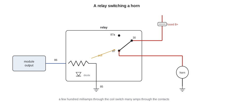
A relay is a switch operated by an electromagnet. A small current through the relay's coil creates a magnetic field that pulls an armature and closes a set of heavy contacts, which then switch a much larger current. Relays let a small switch or a module's output control a heavy load, such as a fuel pump, a blower, a horn or a rear defroster, without that load's current passing through the switch or the module. The standard automotive relay has four or five terminals numbered by a common European convention: 85 and 86 are the coil, 30 is the common contact connected to power, 87 is the normally open contact and 87a, on a five-pin relay, the normally closed contact.
When a relay's coil is switched off, its collapsing magnetic field produces a voltage spike that can damage a module output. Most relays used with modules have a diode or a resistor across the coil to absorb the spike, which also means the coil's polarity matters: connecting a diode-suppressed relay coil backwards can short the module's output through the diode. A relay with a buzzing coil and no contact closure usually has low coil voltage; a relay that clicks but does not power the load usually has burnt contacts. Swapping a suspect relay with an identical one from a non-critical circuit is a quick test, but the voltage drop across the contacts while they carry the load is the definitive one, typically no more than about 0.2 to 0.3 volts.
# Relay check: coil current from coil resistance, and the contact voltage drop under load
coil_ohm = 85.0
supply = 13.5
print(f"coil current {supply / coil_ohm * 1000:4.0f} mA (what the module output must switch)")
load_a = 18.0                      # rear defroster through the relay contacts
for name, drop in [("new relay", 0.06), ("customer relay", 0.71)]:
    heat = load_a * drop
print(f"{name:<15} contact drop {drop:4.2f} V at {load_a:4.1f} A -> {heat:4.1f} W heating the contacts: " + ("ok" if drop <= 0.3 else "replace"))coil current 159 mA (what the module output must switch) new relay contact drop 0.06 V at 18.0 A -> 1.1 W heating the contacts: ok customer relay contact drop 0.71 V at 18.0 A -> 12.8 W heating the contacts: replace
The body control module
On most current vehicles, the body control module, or BCM, sits at the center of the body electrical system. It reads switches, such as the headlamp switch, turn signal stalk, door ajar switches and lock switches, and it drives lamps, locks, wipers and relays directly through solid-state outputs or indirectly by sending commands over the network to other modules. Some switches are wired as simple on-off inputs; many, such as multi-function stalks, are resistor ladders, in which each switch position connects a different resistor and the module reads the voltage to decide which position is selected. Others send their status over a LIN network. Because the BCM sees and controls so much, the scan tool's BCM data and output tests are among the most useful tools for body electrical diagnosis.
Motors: windows, locks, mirrors and wipers
Power windows, locks and mirrors use small permanent magnet DC motors. Reversing the polarity of the supply reverses the motor's direction, so a window switch is wired to send power one way for up and the other way for down, with both motor wires grounded through the switch at rest. Many windows now have a door module that drives the motor directly, counts pulses from a sensor on the motor to know the window's position, and reverses the window if it meets an obstruction while closing automatically. After a battery disconnect or a motor replacement, those windows need a position relearn, often done by running the window fully up and holding the switch for a few seconds.
Harold Kemp's window goes down but not up. Kiran's first test is the scan tool's door module data: the module sees the up switch request. The output test commands the motor up, and nothing happens, while the down test works. With the door panel off, she back-probes the motor connector: in the up direction the module outputs 12.6 volts on one wire, but the other wire, which should be grounded through the module in that direction, reads 12.4 volts to ground, meaning the ground is not being completed. The module's internal low-side driver for that direction has failed. A replacement door module, programmed to the vehicle with the scan tool and given a window relearn, fixes it.
Wiper motors usually have two speeds, using a third brush, plus a park switch inside the motor that keeps it running until the wipers reach their rest position. Intermittent and rain-sensing wipers are controlled by the BCM or a wiper module. A wiper that stops anywhere on the glass when switched off points to the park switch circuit, and one that runs only on high points to the low-speed brush or its circuit.
Heated elements
Rear window defrosters, heated mirrors, seats and steering wheels are resistive loads, often controlled by a module through a relay or a solid-state driver with a timer, and sometimes with a temperature sensor. A rear defroster grid can be checked line by line with a voltmeter while it is on: the voltage along a good grid line falls smoothly from about 12 volts at the feed side to zero at the ground side, while a broken line shows full voltage on one side of the break and zero on the other. Small breaks can be repaired with a conductive repair compound. Ines's heated mirror has 12.4 volts at its connector when switched on, but its element reads open on the ohmmeter; the element is part of the mirror glass, so the glass is replaced.
Worked problem
Why does the LED bulb cause hyperflash?
A turn signal output normally drives a 21 W filament bulb at 13.5 V. The module flags a failed bulb if the current falls below 1.0 A. An aftermarket LED bulb draws 0.18 A. What does the module see?
Show solution
- Filament bulb current: I = P / V = 21 / 13.5 ≈ 1.56 A, above the threshold.
- LED bulb current: 0.18 A, far below 1.0 A.
- The module concludes that the bulb has failed.
- It flashes at double speed to warn the driver: hyperflash.
Answer: 0.18 A looks like a burnt bulb, so the module triggers hyperflash.
Common mistakes
MistakeFixing hyperflash with a load resistor taped to the lamp housing.
InsteadFit the correct bulbs or an approved replacement; resistors get hot enough to melt housings.
MistakeWorking on an HID headlamp with the lamp switched on.
InsteadThe starting pulse is over 20,000 V; isolate the circuit first.
MistakeReading a PWM lamp circuit with a DC voltmeter and calling it low.
InsteadUse the duty cycle function or a scope.
MistakeReversing the coil connections of a diode-suppressed relay.
InsteadPolarity matters; a reversed diode can short the module output.
MistakeReplacing a window motor without checking the module's outputs.
InsteadBack-probe both motor wires in each direction first.
Summary and key terms
- Filament bulbs are resistive loads with a large inrush current; LEDs use far less current and need current limiting.
- Bulb-out detection measures current; low-current LED bulbs can trigger hyperflash.
- HID headlamps use dangerous starting voltages; LED headlamps use drivers and may be adaptive.
- Modules dim lamps with pulse-width modulation, varying the duty cycle.
- Relays let a small coil current switch a heavy load; terminals 85 and 86 are the coil, 30 and 87 the contacts.
- The BCM reads switches, often as resistor ladders, and drives body loads directly or over the network.
- Window, lock and mirror motors reverse by polarity; heated elements are checked by voltage along the element.
- LED
- A light-emitting diode, a semiconductor that emits light when current flows forward through it.
- Inrush current
- The high current a cold filament or motor draws for an instant when switched on.
- Hyperflash
- Double-speed flashing of the turn signals that warns of a failed bulb.
- Pulse-width modulation
- Switching a load on and off rapidly and varying the on-time to control its average power.
- Relay
- An electromagnetically operated switch that lets a small current control a large one.
- Body control module
- The module that reads body switches and controls lamps, locks, wipers and other body loads.
- Resistor ladder
- A switch circuit in which each position connects a different resistor, read as a voltage.
Practice problems
Work each problem on paper first, then reveal the answer to check.
Which relay terminals are the coil?
Show answer
85 and 86.
Why do brake lamps benefit from LEDs?
Show answer
LEDs light almost instantly, giving following drivers more warning.
A wiper stops wherever it is when switched off. Which circuit should be checked?
Show answer
The park switch circuit.
How can a broken rear defroster line be found?
Show answer
With the defroster on, follow the line with a voltmeter; the voltage jumps across the break.
Lesson quiz · 5 questions
Score 60% or more to complete this lesson.
Create a free account to save your progress, take quizzes and earn a certificate.