
AUTO-220 · Lesson 10 of 12 · 20 min
Electronic modules, sensors and actuators
A modern vehicle may have 30 to more than 100 electronic control modules, and most of what Kiran used to think of as "electrical" now passes through one of them. This week's lesson arrives in the form of Gord Haney's pickup again, which comes in on a flatbed with a strange set of symptoms: the oil pressure gauge reads zero, the fuel gauge reads empty although the tank is half full, and the engine runs but the dash shows a reduced power warning. "Three gauges dead at once, and none of them share a sensor," says Kiran. Marty smiles. "But maybe they share something else. Let's look at how modules read sensors."
This lesson covers what a control module is and how it works, the reference voltages, pull-up resistors and grounds that sensor circuits depend on, the main kinds of sensor and how each one makes its signal, how modules drive actuators with high-side and low-side drivers and pulse-width modulation, an introduction to scope patterns, and the care modules need when they are replaced. Module programming and driveability diagnosis are covered in AUTO-330.
What a module does
Every control module works the same basic way. It reads inputs from sensors and switches, processes them with a microcontroller running software and stored calibration data, and drives outputs to actuators such as injectors, motors, relays, lamps and solenoids. Most modules also share information with other modules over a network, which is the subject of Lesson 11. Inside, a module has power supply circuits that turn battery voltage into the steady 5-volt and 3.3-volt supplies its electronics need, input circuits that condition each sensor signal, the microcontroller, output drivers and network transceivers.
Modules depend on good power and ground. A module with low supply voltage or a poor ground can reset, lose communication or misread its sensors, and many baffling faults turn out to be a corroded module ground. Before suspecting a module, Kiran checks every power and ground pin the diagram shows, under load, with the module awake.
Reference voltage and signal circuits
Most sensors are connected to their module by two or three wires. A three-wire sensor has a reference voltage, usually 5 volts, supplied by the module; a low reference or sensor ground, returned to the module rather than to the body; and a signal wire back to the module. A two-wire sensor has only a signal wire and a low reference. Because the module supplies both the reference and the ground, the signal is measured against a clean, steady supply, unaffected by changes in battery voltage or the noise on body grounds.
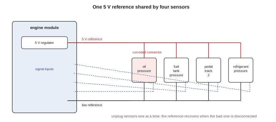
To save pins, a module usually feeds one 5-volt reference circuit to several sensors at once. That is exactly what happened on Gord's truck. Kiran checks the diagram and finds that the oil pressure sensor, the fuel tank pressure sensor, the accelerator pedal's second track and the air conditioning pressure sensor all share one 5-volt reference circuit from the engine control module. On the scan tool, all four read zero or at their limits, and the module has stored a code for the reference circuit being low. Back-probing the oil pressure sensor's reference pin shows 0.2 volts instead of 5. She disconnects the sensors one at a time, watching the reference voltage. When she unplugs the oil pressure sensor, the reference jumps to 4.98 volts and the other gauges come alive. The sensor's connector is wet inside: its seal has split, and corrosion has bridged the reference and ground terminals. A new sensor and a new pigtail cure all three symptoms.
Pull-up resistors and thermistors
Many two-wire sensors work with a pull-up resistor inside the module. The module connects its 5-volt supply to the signal wire through a fixed resistor, typically a few thousand ohms, and the sensor connects the signal wire to ground through its own resistance. The two resistances form a voltage divider: the signal voltage depends on the ratio of the sensor's resistance to the pull-up's. A coolant temperature sensor is a negative temperature coefficient thermistor, whose resistance falls as it warms, so the signal voltage falls from near 5 volts when the engine is very cold to below 1 volt when it is hot. The pull-up also gives the module a way to detect faults: an open sensor or wire pulls the signal to almost 5 volts, and a short to ground pulls it to almost zero.
# Coolant temperature sensor: thermistor resistance and the module's pull-up divider (illustrative values)
import math
pullup = 2490.0                   # ohm inside the module
vref = 5.0
def ntc(temp_c, r25=2050.0, beta=3450.0):
    t = temp_c + 273.15
    return r25 * math.exp(beta * (1 / t - 1 / 298.15))
UNITS = "US"
for temp in (-30, -10, 20, 50, 90, 105):
    r = ntc(temp)
    v = vref * r / (r + pullup)
    label = f"{temp:4d} C" if UNITS == "metric" else f"{temp * 9 / 5 + 32:4.0f} F"
    print(f"{label}: sensor {r:8.0f} ohm, signal {v:4.2f} V")
print("open sensor or wire: signal near 5.0 V; shorted to ground: near 0.0 V")-22 F: sensor 28086 ohm, signal 4.59 V 14 F: sensor 9553 ohm, signal 3.97 V 68 F: sensor 2497 ohm, signal 2.50 V 122 F: sensor 837 ohm, signal 1.26 V 194 F: sensor 258 ohm, signal 0.47 V 221 F: sensor 177 ohm, signal 0.33 V open sensor or wire: signal near 5.0 V; shorted to ground: near 0.0 V
Kinds of sensor
A potentiometer is a variable resistor with a wiper that slides along a resistive track. With 5 volts across the track, the wiper's voltage tells the module the position: throttle plates, pedals, seat positions and some ride height sensors have used potentiometers, though many are now replaced by non-contact Hall-effect sensors that do not wear. Accelerator pedals and electronic throttles use two independent sensor tracks, often with different ranges, so that the module can compare them and detect a fault.
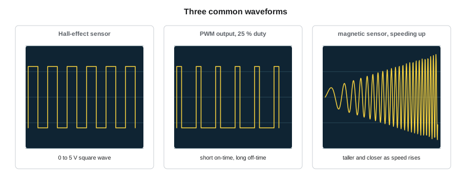
A magnetic or variable reluctance sensor has a coil around a magnet. As the teeth of a reluctor wheel pass its tip, the changing magnetic field induces an AC voltage whose frequency rises with speed and whose size also grows with speed. Older crankshaft and wheel speed sensors work this way, and they need no power supply. A Hall-effect sensor uses a semiconductor that switches its output when a magnetic field passes it; it needs a power supply and produces a clean on-off square wave whose size does not change with speed, so it works down to zero speed. Many current wheel speed sensors are active sensors that send a current signal, switching between two levels such as 7 and 14 milliamps, and some encode extra information, such as the direction of rotation.
Pressure sensors use a silicon diaphragm with strain gauges and built-in electronics, producing a voltage between about 0.5 and 4.5 volts across their range; the gap at each end lets the module tell a real reading from an open or shorted circuit. Oxygen and air-fuel ratio sensors, knock sensors and mass airflow sensors have their own operating principles and are covered in AUTO-230 and AUTO-330. Many newer sensors, called smart sensors, process their own signal and send it to the module digitally, using a protocol such as SENT, which a meter cannot read; a scope or the scan tool must be used.
Actuators and drivers
A module switches its outputs with transistors called drivers. A low-side driver switches the ground side of the load: the load has battery power all the time it is switched on by the ignition, and the module completes the circuit to ground to turn it on. Fuel injectors, many relays and many solenoids are low-side driven. A high-side driver switches the power side: the load is permanently grounded, and the module supplies power to turn it on. High-side drivers are common for lamps, heaters and sensors' power supplies. Some loads, such as electronic throttle motors and power window motors, use an H-bridge, four drivers that can apply power in either direction to run a motor both ways.
Knowing which side is switched matters for testing. On a low-side driven injector, a test light connected between the injector's control wire and battery positive flickers when the module pulses it; on a high-side circuit, the test light goes to ground. But test lights must not be used on circuits the service information warns about, as Lesson 2 explained, and most modern drivers have built-in current monitoring and fault detection, so the module may shut an output off and set a code if it sees a short or an open. The scan tool's output tests, which let the technician command each output on and off, are often the safest way to check a driver and its circuit together.
# Pulse-width modulation: average voltage and current from the duty cycle
supply = 13.6
load_ohm = 4.0                         # e.g. a fan motor winding, illustrative
for duty in (10, 25, 50, 75, 100):
    v_avg = supply * duty / 100
    print(f"duty {duty:3d} %: average {v_avg:5.2f} V, average current {v_avg / load_ohm:4.2f} A")
period_ms = 1000 / 250                 # 250 Hz switching
print(f"at 250 Hz each cycle lasts {period_ms:.1f} ms; at 50 % the output is on for {period_ms / 2:.1f} ms")duty 10 %: average 1.36 V, average current 0.34 A duty 25 %: average 3.40 V, average current 0.85 A duty 50 %: average 6.80 V, average current 1.70 A duty 75 %: average 10.20 V, average current 2.55 A duty 100 %: average 13.60 V, average current 3.40 A at 250 Hz each cycle lasts 4.0 ms; at 50 % the output is on for 2.0 ms
Seeing signals with a scope
A DMM shows one number, updated a few times per second, and averages anything faster. A lab scope, or oscilloscope, draws a graph of voltage against time, so a technician can see a sensor's waveform, a driver's switching, or a dropout that lasts a few thousandths of a second. A Hall-effect crankshaft sensor's signal on a scope is a square wave with sharp edges; a pulse-width modulated output is a square wave whose on-time varies; a magnetic sensor's signal is a wave that grows taller and closer together as speed rises. Glitches, missing teeth, noise and slow edges, all invisible to a meter, show clearly. Kiran's scope work will grow in AUTO-330; for now, Marty has her capture a few known-good patterns from shop vehicles and save them as references.
Replacing and handling modules
Modules are sensitive to static electricity, which can damage their circuits without any visible sign. Kiran touches a grounded metal point before handling a module, does not touch connector pins, and keeps replacement modules in their antistatic packaging until fitting them. The battery is disconnected, or the procedure in the service information followed, before unplugging a module. Most replacement modules must be programmed or configured for the vehicle, with its VIN, options and security data, before they will work, and some must be paired with other modules or the immobilizer. That work needs the correct scan tool and often online access to the manufacturer's service systems, as Lesson 11 explains for secured vehicles.
Before ordering a module, the shop proves that it has failed: power, grounds, inputs and outputs have been checked; the wiring and connectors are good; the module's software level has been checked against any update the manufacturer has released; and, for an expensive module, the shop's diagnostic notes show why nothing else could cause the fault. A module that is replaced because of a corroded ground or a shorted sensor will fail again, or the new one will be damaged.
Worked problem
Is the sensor or the wiring at fault?
A coolant temperature sensor reads −40 °F on the scan tool on a warm engine. The signal wire measures 4.96 V at the module with the sensor connected. With the sensor unplugged and a jumper wire across its connector pins, the scan tool reads very hot. What has failed?
Show solution
- −40 is the reading the module shows for a signal near 5 V, which means an open circuit.
- With the sensor unplugged and the pins jumpered, the signal is pulled to ground and the reading goes very hot.
- So the wiring and the module can see a change at the connector.
- The open is inside the sensor, which is replaced.
Answer: The sensor itself is open; the wiring and module respond correctly.
Common mistakes
MistakeReplacing several sensors because several readings are wrong.
InsteadLook for something they share, such as a reference circuit or ground.
MistakeMeasuring a sensor's ground to the body instead of to the module's low reference.
InsteadMany sensors return to the module; follow the diagram.
MistakeTrying to read a digital smart sensor with a meter.
InsteadUse a scope or the scan tool.
MistakeHandling a module's pins without static precautions.
InsteadGround yourself, keep it in its antistatic bag and avoid touching pins.
MistakeOrdering a module before testing its power, grounds, inputs and outputs.
InsteadProve the module has failed; most module complaints are wiring.
Summary and key terms
- Modules read inputs, process them with software and calibrations, and drive outputs.
- Three-wire sensors use a module's 5 V reference, low reference and a signal wire; references are often shared.
- Two-wire sensors such as thermistors work with a pull-up resistor in the module.
- Potentiometers, magnetic, Hall-effect, active, pressure and smart sensors make different kinds of signal.
- Low-side drivers switch ground, high-side drivers switch power, H-bridges run motors both ways.
- Pulse-width modulation controls average power by varying the duty cycle.
- Scopes show waveforms a meter cannot; modules need static care and programming when replaced.
- Reference voltage
- A steady supply, usually 5 V, that a module provides to its sensors.
- Pull-up resistor
- A resistor inside the module between its supply and a sensor's signal wire.
- Thermistor
- A resistor whose resistance changes with temperature, used for temperature sensing.
- Hall-effect sensor
- A powered sensor that switches its output as a magnetic field passes, giving a square wave.
- Low-side driver
- A module output that switches a load's ground side.
- High-side driver
- A module output that switches a load's power side.
- Duty cycle
- The percentage of each cycle that a switched output is on.
Practice problems
Work each problem on paper first, then reveal the answer to check.
A three-wire sensor's reference reads 0.3 V. What should be done next?
Show answer
Unplug the sensors sharing that reference one at a time to find the one pulling it down.
Why do pressure sensors read about 0.5 to 4.5 V rather than 0 to 5 V?
Show answer
So the module can tell real readings from an open or a short.
Which kind of sensor needs no power supply?
Show answer
A magnetic, variable reluctance sensor.
A fan is driven at 40 % duty from 13.5 V. What is the average voltage?
Show answer
About 5.4 V.
Lesson quiz · 5 questions
Score 60% or more to complete this lesson.
Create a free account to save your progress, take quizzes and earn a certificate.