
AUTO-220 · Lesson 12 of 12 · 20 min
Capstone: tracking down a parasitic draw and a network fault
In January, Hal Osei brings Ridgeline the fleet's most frustrating problem yet. Courier van 3 has needed a boost on four of the last five Monday mornings after sitting in the depot lot over the weekend, and on two of those mornings the dash also showed an anti-lock brake warning and a stability control warning that cleared after a restart. The battery is only a year old. Another shop replaced the alternator in November, which changed nothing. Hal's vans had a new fleet telematics system fitted in October: a small box that reports each van's location, mileage and fault codes to Hal's office over the cellular network. Bev assigns the van to Kiran, with Marty as her check, and tells Simone to quote Hal for three hours of diagnosis to start.
This capstone uses everything in the course: the interview, the battery and charging tests, the meter and clamp, the wiring diagram, the voltage drop method, module behavior and the network. It covers a parasitic draw test from start to finish, how modules go to sleep, how to find a draw without pulling fuses, and how to find an intermittent network fault, and it ends with the repairs, the verification and the report to the customer.
Step 1: the interview and the plan
Kiran starts by asking questions, not by connecting tools. The no-starts happen only after the van sits for more than about 40 hours; it starts fine overnight. The other vans with the same telematics box do not have the problem, though van 3 is the only one whose box was fitted by a different installer on a busy day. The ABS warnings have appeared only on cold mornings after rain or slush. Marcus Bell, who sometimes drives van 3, adds that the dome lamp once stayed on after he locked the van. Kiran writes the two complaints separately, because they may or may not be related: a battery drain over a weekend, and an intermittent network or ABS fault.
Her plan is to test the battery and charging system first, so that she knows the battery is not simply worn; then to measure the van's sleep current properly; then to find what is keeping the van awake; and finally to diagnose the ABS warnings with the scan tool and the network tests from Lesson 11.
Step 2: battery and charging
The battery, an AGM unit, is at 61 percent charge when the van arrives. After a full charge and a rest, it reads 12.84 volts and passes the conductance test at 698 measured CCA against a 720 rating. The alternator, the one replaced in November, delivers 196 amps against a 210-amp rating with 0.21 volts of ripple, and the charging circuit's voltage drops are small. The scan tool shows that the battery monitoring sensor was never reset after the battery was replaced last year, so Kiran notes that the registration must be done as part of the repair. The battery and charging system are healthy; something is draining the battery while the van is parked.
Step 3: measuring the parasitic draw
A parasitic draw is the current that flows from the battery when the vehicle is switched off. Some draw is normal: the clock, the keyless entry receiver, the alarm and the modules' memories need a little current, and a modern vehicle's modules take time to go to sleep after it is switched off. Many vehicles keep their networks awake for anything from a few seconds to 45 minutes or more after the doors are locked, while modules finish tasks such as checking the evaporative emissions system, cooling the turbocharger or reporting to a telematics server. Once asleep, a typical vehicle draws between about 20 and 50 milliamps, though the specification for each model in the service information is the real limit.
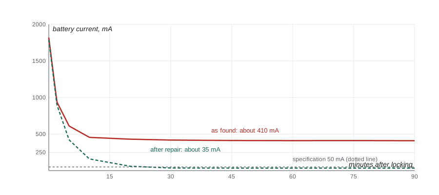
The test must not wake the van up, or it will never sleep. Kiran connects a low-current DC clamp, zeroed, around the battery negative cable, which avoids breaking the circuit; on vehicles where a clamp is not sensitive enough, a meter in series through a battery disconnect switch with a bypass is used, so that the circuit is never interrupted. She latches the hood switch closed so the van thinks the hood is shut, closes the doors with the latches tricked shut on the driver's door so that she can reach inside, locks the van with the fob, puts the fob well away from the vehicle, and waits, recording the current every few minutes.
# Sleep current after locking: does the van settle to its specification? (readings every few minutes)
spec_ma = 50
readings = [(0, 1820), (2, 940), (5, 610), (10, 455), (20, 430), (30, 418), (45, 412), (60, 410), (75, 411), (90, 409)]
for minutes, ma in readings:
    bar = "#" * min(60, ma // 30)
    print(f"{minutes:3d} min {ma:5d} mA {bar}")
final = readings[-1][1]
print(f"settled at {final} mA against a specification of {spec_ma} mA: {'normal' if final <= spec_ma else 'excessive draw'}")
cap_ah, usable = 80.0, 0.5
print(f"at {final} mA an {cap_ah:.0f} Ah battery loses half its charge in about {cap_ah * usable / (final / 1000):4.0f} h")0 min 1820 mA ############################################################ 2 min 940 mA ############################### 5 min 610 mA #################### 10 min 455 mA ############### 20 min 430 mA ############## 30 min 418 mA ############# 45 min 412 mA ############# 60 min 410 mA ############# 75 min 411 mA ############# 90 min 409 mA ############# settled at 409 mA against a specification of 50 mA: excessive draw at 409 mA an 80 Ah battery loses half its charge in about 98 h
The current drops quickly at first as lamps and modules shut down, but it never settles below about 410 milliamps, against a specification of 50 milliamps. At that rate, an 80 ampere-hour battery loses half its charge in about 98 hours, roughly four days; starting from a partly discharged battery after a week of short courier trips in the cold, a weekend is enough to leave it unable to crank. The draw is real, and it explains the Monday no-starts.
Step 4: is the network asleep?
A draw of 400 milliamps is more than any single small memory circuit; it suggests that modules are still awake. Kiran checks the network without disturbing the van. With a scope connected to CAN high and CAN low at the diagnostic connector, through back-probes so that no connector is unplugged, she sees continuous traffic an hour after locking. An asleep CAN network sits quietly with both lines near zero or at a steady level; this one is busy, with a short burst of frames every few seconds and a longer burst every 30 seconds. Something is talking on the network and keeping every module awake.
Step 5: finding the draw without pulling fuses
The traditional way to find a draw is to pull fuses one at a time until the current drops. On a modern vehicle, that is a poor method: pulling a fuse can wake modules, reset the sleep timers and change the very behavior being tested, and reinstalling it can wake the network again. Instead, Kiran measures the tiny voltage drop across each fuse with the meter on its millivolt range, without removing anything. Every fuse has a small resistance, so the current through it produces a small voltage drop; a fuse chart, available from several sources and in some service information, converts that drop into current for each fuse type and rating. Fuses feeding circuits that are asleep read zero; the fuse feeding the draw reads a few millivolts.
# Fuse voltage drop to current: I = V / R, using each fuse's cold resistance (illustrative values)
fuse_mohm = {"5 A mini": 22.0, "10 A mini": 9.5, "15 A mini": 6.0, "20 A mini": 4.4, "25 A mini": 3.5}
measured = [("F12 radio and display", "10 A mini", 0.0), ("F21 body control module", "15 A mini", 0.4),
            ("F33 diagnostic connector power", "20 A mini", 1.45), ("F07 instrument cluster", "5 A mini", 0.2),
            ("F40 brake module", "25 A mini", 0.0)]
for name, kind, mv in measured:
    ma = mv / fuse_mohm[kind] * 1000
    flag = "  <- most of the draw" if ma > 200 else ""
print(f"{name:<34} {kind:<10} {mv:5.2f} mV -> {ma:5.0f} mA{flag}")F12 radio and display 10 A mini 0.00 mV -> 0 mA F21 body control module 15 A mini 0.40 mV -> 67 mA F33 diagnostic connector power 20 A mini 1.45 mV -> 330 mA <- most of the draw F07 instrument cluster 5 A mini 0.20 mV -> 9 mA F40 brake module 25 A mini 0.00 mV -> 0 mA
The diagnostic connector's power fuse shows the largest drop, worth about 330 milliamps. The diagram shows that the connector's pin 16, battery power, is on that fuse, and the telematics box is plugged into the diagnostic connector through a splitter cable under the dash. With Hal's permission, Kiran checks the box's installation guide on the supplier's website: the box is meant to be wired to a switched power source and to stop polling the network once the ignition has been off for five minutes, using a setting the installer chooses. Van 3's box is set to always on, and it requests data from the modules every 30 seconds. Each request wakes the network, the modules answer, and the sleep timers restart, so the van never sleeps.
Kiran confirms it by unplugging the splitter cable at the diagnostic connector, having first let the van settle with the box connected. The scope shows the network go quiet within two minutes, and the current falls to 38 milliamps 25 minutes later, inside the specification. The box was causing the draw, both directly, at about 330 milliamps, and indirectly, by keeping the modules awake.
Step 6: the network fault
The ABS and stability warnings need a separate diagnosis. The stored codes show the brake module lost communication with the engine module and the instrument cluster on two dates, and the cluster and engine module each have a U code for lost communication with the brake module. Only the brake module is ever missing, so the fault is probably in its own connection to the network, its power or its ground, not in the whole network. With the network asleep, Kiran measures 60 ohms between CAN high and CAN low at the diagnostic connector, which is normal; at the brake module connector, the same measurement is 60 ohms. Wiring and terminations look good, at least while the van sits dry and warm in the shop.
The weather is the clue. The warnings happen after slush, and the brake module sits low on the left frame rail. Kiran inspects the brake module's connector and harness: the connector is sealed and clean, but 30 centimeters away, where the harness passes over the frame rail, its protective conduit has worn through against a bracket, and the insulation of the CAN low wire is chafed down to the copper. When she sprays the area with a light mist of salt water from a spray bottle while watching the scan tool and the scope, the brake module drops off the network within seconds and the scope shows CAN low being dragged toward ground. The wet chafed wire was leaking to the frame, enough to disrupt the brake module's messages when the road was wet.
# Network checks at the brake module, dry and wet (asleep resistance and awake voltages)
checks = [("dry", 60, 2.61, 2.39), ("wet, salt mist on chafed harness", 58, 2.60, 0.92)]
for state, ohms, can_h, can_l in checks:
    diff = can_h - can_l
    print(f"{state:<34} H-L {ohms:3d} ohm, CAN high {can_h:4.2f} V, CAN low {can_l:4.2f} V, idle difference {diff:4.2f} V")
print("CAN low pulled toward ground when wet: leakage to the frame at the chafe")dry H-L 60 ohm, CAN high 2.61 V, CAN low 2.39 V, idle difference 0.22 V wet, salt mist on chafed harness H-L 58 ohm, CAN high 2.60 V, CAN low 0.92 V, idle difference 1.68 V CAN low pulled toward ground when wet: leakage to the frame at the chafe
Step 7: repairs and verification
With Hal's approval of the estimate, the repairs are straightforward. Kiran repairs the chafed CAN low wire with an approved sealed splice, keeping the twisted pair's twist up to the splice as Lesson 4 described and staying within the manufacturer's limit on untwisted length, and she checks CAN high for damage too. She refits new conduit, tapes the harness, and relocates it with a new clip so that it no longer touches the bracket. For the telematics box, she removes the splitter cable and reconnects the box to the diagnostic connector through the supplier's harness with the ignition-sense wire connected to a switched fuse circuit, as the guide requires, and sets the box's sleep timer to five minutes. Hal's office confirms the box is still reporting while the van is in use.
Verification takes two forms. For the draw, she repeats the sleep current test with the box connected and configured: the current falls to 35 milliamps within 30 minutes and stays there, and the scope shows the network asleep. For the network, she sprays the repaired area with the same salt mist, drives the van through the shop's wash bay and a 15-minute road test with the scan tool recording, and sees no lost-communication events. She registers the battery with the battery management system, clears all codes, and checks the stored codes again the next morning after the van has sat outside overnight.
Step 8: the report
Kiran's report on the repair order follows the three Cs: complaint, cause and correction. Complaint: no-start after weekends and intermittent ABS and stability warnings in wet weather. Cause: a telematics box connected to constant power and set to poll the network continuously, which kept the vehicle's modules awake and drew 410 milliamps against a 50-milliamp specification; and a CAN low wire chafed through its insulation at the left frame rail, which leaked to the frame when wet. Correction: telematics box rewired and configured per the supplier's guide, chafed wire repaired with an approved sealed splice and rerouted with new conduit and clip, battery registered, sleep current verified at 35 milliamps and network verified wet and on a road test.
# Repair order totals for van 3 (labor hours at the shop rate; tax as described for each site)
labor_rate = 155.00
lines = [("diagnosis: parasitic draw and network", 2.6), ("wiring repair, CAN low, conduit and clip", 0.8),
         ("telematics harness reconnection and setup", 0.5), ("battery registration and verification", 0.4)]
parts = [("sealed splice kit", 16.90), ("conduit, tape and clip", 20.95)]
lab = sum(h for _, h in lines) * labor_rate
par = sum(p for _, p in parts)
for name, h in lines:
    print(f"{name:<44} {h:3.1f} h  {h * labor_rate:8.2f}")
for name, p in parts:
    print(f"{name:<44}        {p:8.2f}")
tax = 0.0915 * par
print(f"labor {lab:.2f}, parts {par:.2f}, sales tax 9.15 % on parts {tax:.2f}, total {lab + par + tax:.2f} USD")diagnosis: parasitic draw and network 2.6 h 403.00 wiring repair, CAN low, conduit and clip 0.8 h 124.00 telematics harness reconnection and setup 0.5 h 77.50 battery registration and verification 0.4 h 62.00 sealed splice kit 16.90 conduit, tape and clip 20.95 labor 666.50, parts 37.85, sales tax 9.15 % on parts 3.46, total 707.81 USD
Simone calls Hal with the results, and Kiran adds a recommendation for the fleet: have the installer check every van's telematics configuration, since van 3's box was set up differently from the others, and inspect the brake module harness on the other vans of the same model at their next service. Hal books two more vans for the following week. Marty signs off Kiran's diagnosis with one comment on the repair order: "Two faults, one complaint each, and the numbers to prove both. That is electrical work."
Common mistakes
MistakePulling fuses one at a time to find a draw on a modern vehicle.
InsteadMeasure the millivolt drop across fuses in place; pulling fuses wakes modules and resets timers.
MistakeReading the draw before the modules have had time to sleep.
InsteadLock the vehicle, keep the fob away, and wait for the specified sleep time.
MistakeOpening a door or the hood during the test.
InsteadTrick the latches closed beforehand so the vehicle stays asleep.
MistakeTreating two symptoms as one fault without evidence.
InsteadDiagnose each complaint separately and see whether they share a cause.
MistakeTesting a wet-weather network fault only in a dry shop.
InsteadRecreate the condition, such as a salt-water mist, while monitoring.
Summary and key terms
- Interview first: when the fault happens, what changed, and which symptoms are separate.
- Test the battery and charging system before chasing a draw.
- Measure sleep current with a low-current clamp or a protected series meter, without waking the vehicle.
- Compare the settled draw with the specification; modules may take up to 45 minutes or more to sleep.
- A busy network after the sleep time means something is keeping modules awake.
- Find a draw with millivolt drops across fuses instead of pulling them.
- Find intermittent network faults by which modules drop out and by recreating the conditions, then verify and report with the three Cs.
- Parasitic draw
- Current drawn from the battery while the vehicle is switched off.
- Sleep current
- The settled current a vehicle draws once all its modules are asleep.
- Sleep timer
- The time a module or network stays awake after the vehicle is switched off or locked.
- Fuse voltage drop method
- Finding the current through a fuse from the millivolt drop across it, without removing it.
- Telematics
- A system that reports a vehicle's location and data over a cellular network.
- Three Cs
- Complaint, cause and correction, the standard structure of a repair order.
- Chafe
- Wear of wire insulation by rubbing against a bracket or edge.
Practice problems
Work each problem on paper first, then reveal the answer to check.
A vehicle settles at 45 mA against a 50 mA specification after 30 minutes. Is there a draw problem?
Show answer
No, it is within specification.
Why does an 80 Ah battery with a 400 mA draw go flat over a long weekend?
Show answer
It loses about 0.4 A × 72 h ≈ 29 Ah, a large share of its usable capacity, especially if it started partly charged.
A 10 A mini fuse with about 9.5 mΩ of resistance shows 1.9 mV across it. About how much current flows?
Show answer
1.9 / 9.5 = 0.2 A, about 200 mA.
Only one module drops off the network in wet weather. Where should the inspection focus?
Show answer
That module's own connector, harness and branch, especially where the harness could chafe or let water in.
Lesson quiz · 5 questions
Score 60% or more to complete this lesson.
Create a free account to save your progress, take quizzes and earn a certificate.