
AUTO-220 · Lesson 2 of 12 · 20 min
Digital multimeters and electrical measurement
Kiran's first electrical job of the autumn is not a repair at all. Marty hands her the shop's training board, a sheet of plywood with a battery, a fuse block, switches, a lamp, a small motor and a few deliberately faulty connectors, and tells her to measure everything on it before lunch. "A meter tells you the truth," he says, "but only if you ask it the right question in the right way. Most bad diagnosis I have seen started with a good meter used wrongly." Theo Banks, who is three years into his apprenticeship, admits he once spent an hour chasing a fault that turned out to be a meter lead plugged into the wrong jack.
This lesson covers the digital multimeter, or DMM: its safety ratings, how to measure voltage, resistance and current, how to use an amp clamp, why a test light and a meter answer different questions, and the habits that keep readings honest. Lab scopes, which show how a voltage changes over time, are introduced in Lesson 10 and covered fully in AUTO-330.
Choosing and trusting a meter
An automotive DMM measures DC and AC volts, resistance, and current, usually up to 10 amps through its leads; most also test diodes and continuity, and many add frequency, duty cycle and temperature. A good meter has high input impedance, typically 10 million ohms on its voltage ranges, so that connecting it barely disturbs the circuit being measured. That matters on computer circuits, where an old analog meter or a cheap test light could load a 5-volt sensor signal enough to change it, or even damage a module output.
Every meter also carries a measurement category rating, such as CAT III 600 V or CAT IV 600 V, printed near the input jacks. The category describes how well the meter and its leads withstand a voltage spike without failing dangerously. A 12-volt car system cannot produce a dangerous spike on its own, but the same meter may be used on the shop's building wiring or, by a technician with the right training, near a hybrid's high-voltage system, so the shop buys meters and leads rated for the worst place they could end up. Damaged leads, cracked probes or a meter with a broken case are taken out of service.
Before trusting a reading, Kiran checks the meter itself. She touches the leads together on the ohms range and expects a reading near zero, typically 0.1 to 0.3 ohms for the leads; that lead resistance is subtracted from low resistance readings, or zeroed out with the meter's relative button. She checks the battery indicator, because a weak meter battery can give wrong readings. And she checks a known voltage, such as a healthy battery, before relying on the meter to tell her a circuit is dead.
Measuring voltage
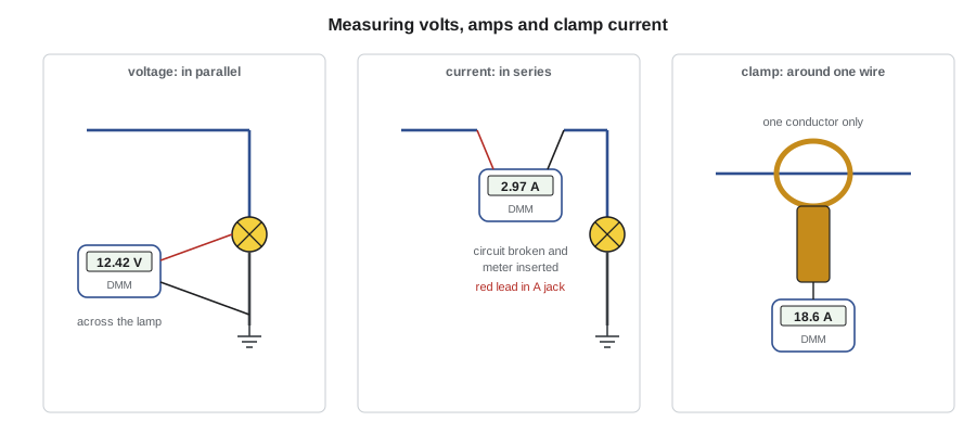
Voltage is measured in parallel: the meter's leads go across the two points of interest while the circuit is working. The black lead goes in the COM jack and the red lead in the V jack. For a reading of the voltage available at a component, the red lead touches the component's power terminal and the black lead a good ground, often the battery negative post. The meter shows the difference between the two points, with a minus sign if the leads are reversed.
Voltage readings tell the most when the circuit is loaded. A wire with a broken strand or a corroded terminal can show full battery voltage with the switch off, or with the load disconnected, because no current flows and so no voltage is lost along the way. As soon as the load draws current, the bad spot drops voltage and the load gets less. That is why Kiran learns to measure with the circuit on and the load connected whenever she can, by back-probing the connector from behind with a fine probe, or by using a breakout lead, instead of unplugging the component and measuring at an open terminal.
Measuring resistance and continuity
Resistance is measured with the circuit unpowered, because the meter supplies its own small test current and reads the voltage it produces. Measuring ohms on a live circuit gives a meaningless number and can damage the meter. The component being tested is usually isolated, disconnected at one end at least, so that the meter reads only that part and not other paths through the vehicle's wiring.
Ohm readings are good for checking components with a known resistance, such as a heater element, a relay coil, a thermistor or a solenoid, against the specification. They are a poor way to check a wire for a high-resistance fault. A wire with only one strand left intact may still read nearly zero ohms with the meter's tiny test current, yet drop several volts when it has to carry 10 amps. The continuity beeper is useful for finding which pin connects to which, but it typically beeps for anything under about 30 to 50 ohms, so a beep does not prove a connection is good. Lesson 3 shows the voltage drop test, which is the right way to find high resistance.
# Wire resistance from length and cross-section (copper at 20 C, illustrative)
RHO = 0.0175                    # ohm mm2 per meter for copper
UNITS = "US"
wires = [(10.0, 18), (10.0, 14), (5.0, 4)]
for length, size in wires:
    if UNITS == "metric":
        area = size                                     # mm2
        r = RHO * length / area
        print(f"{length:4.1f} m of {size:4.2f} mm2 copper: {r * 1000:6.1f} milliohm")
    else:
        area = {18: 0.823, 14: 2.08, 4: 21.2}[size]       # AWG to mm2
        r = RHO * (length * 0.3048) / area
        print(f"{length:4.1f} ft of {size:2d} AWG copper: {r * 1000:6.1f} milliohm")
print("a meter's leads alone read about 100 to 300 milliohm, so zero them first")10.0 ft of 18 AWG copper: 64.8 milliohm 10.0 ft of 14 AWG copper: 25.6 milliohm 5.0 ft of 4 AWG copper: 1.3 milliohm a meter's leads alone read about 100 to 300 milliohm, so zero them first
Measuring current
Current is measured in series: the circuit is broken and the meter is inserted so that the current flows through it. The red lead moves to the A or mA jack, and the meter is set to amps. This is where meters are most often damaged. A meter connected in series has almost no resistance, so if it is accidentally connected across a voltage source while on the amps setting, it becomes a short circuit; the meter's internal fuse blows if it is lucky, and the test leads can melt if it is not. Kiran's habit is to move the red lead back to the V jack the moment she finishes a current reading.
The leads method is limited to about 10 amps, often for 30 seconds or less, so it suits small currents such as a module's sleep current or a lamp circuit. For larger currents, such as a blower motor, a fuel pump or a starter, the shop uses an inductive amp clamp, which measures the magnetic field around a single wire without breaking the circuit. A clamp must go around one conductor only; clamping around a cable with both the supply and the return inside reads nearly zero, because the two fields cancel. DC clamps must be zeroed with the jaws closed and away from any wire before each reading, and low-current clamps can read a few milliamps, which is useful for parasitic draw testing in Lesson 12.
Min/max, hold and frequency
Many DMMs can record the minimum and maximum readings while connected, which helps with faults that come and go. Kiran can connect the meter to a sensor signal, set min/max, and wiggle the harness or drive the vehicle; if the voltage briefly drops out, the minimum reading shows it, even if she did not see it happen. Faster events, such as a dropout lasting a few thousandths of a second, need a meter with a peak or fast min/max mode, or a scope. The frequency and duty cycle functions read switching signals, such as a pulse-width modulated output, but a scope shows them better.
# Reading a meter: what range and resolution do I need? (illustrative autorange steps)
ranges = [(0.6, 0.0001), (6.0, 0.001), (60.0, 0.01), (600.0, 0.1)]
def show(volts):
    for top, res in ranges:
        if abs(volts) < top:
            digits = max(0, len(str(res).split(".")[1]) if "." in str(res) else 0)
            return f"{volts:.{digits}f} V on the {top:g} V range"
    return "over range"
for v in (0.0453, 0.452, 4.98, 12.63, 14.41):
print(f"true value {v:7.4f} -> display {show(v)}")true value 0.0453 -> display 0.0453 V on the 0.6 V range true value 0.4520 -> display 0.4520 V on the 0.6 V range true value 4.9800 -> display 4.980 V on the 6 V range true value 12.6300 -> display 12.63 V on the 60 V range true value 14.4100 -> display 14.41 V on the 60 V range
Test lights and powered probes
A test light is a probe with a bulb or LED and a ground clip. It answers a simple question: is there enough voltage and current here to light a lamp? Because an incandescent test light draws a fraction of an amp, it loads the circuit slightly, which can actually help find a high-resistance fault that a meter would miss. But it must never be used on computer circuits, airbag circuits or sensor signals, because the current it draws can damage a module output or fire an airbag. LED test lights draw much less current, which makes them safer around electronics but less useful for load-testing a circuit. A powered probe can apply battery voltage or ground to a component through a protected tip; it is useful for running a motor directly to see whether it works, but it must be used only where the service information allows.
Marty's view is that a test light is for quick checks of fuses and simple power circuits, and the meter is for measurements. When a diagnosis matters, he wants numbers on the repair order: "12.4 volts at the pump connector with the pump running" tells the next technician something; "test light lit" does not.
Good measurement habits
Kiran writes down a short set of habits on the inside of her toolbox lid. Know what reading to expect before taking it. Measure with the circuit working and the load connected. Measure voltage first, because it is the safest and tells the most. Use the battery negative post, not just any metal, as the ground reference unless the test calls for a local ground. Back-probe with care and never pierce wire insulation, which lets water in and starts corrosion inside the wire. Use breakout leads on sealed connectors instead of forcing a probe past the seal. And when a reading does not make sense, check the meter, the leads and the connection before doubting the vehicle.
By lunch she has found every fault on the training board: a fuse holder with a loose clip that dropped 1.8 volts under load, a switch that read perfectly on ohms but dropped 0.9 volts while carrying the motor's current, and a ground screw that had been painted over. Marty initials her sheet and adds one more line: "Two of these three would have passed a continuity beep test."
Worked problem
Choosing the right measurement
The rear wiper on the Lindqvists' minivan runs slowly. Kiran wants to know how much current the motor draws, which is expected to be about 3 A. Which meter setup should she use, and what must she do afterwards?
Show solution
- The current is under 10 A, so the leads method in series works, or a low-current clamp around the motor's power wire.
- For the leads method she moves the red lead to the A jack, selects DC amps and inserts the meter in series at the fuse or connector.
- She runs the wiper and reads the current, then compares it with the specification.
- Afterwards she moves the red lead back to the V jack so that the next voltage reading does not short the circuit through the meter.
Answer: Measure in series on the amps jack or use a clamp; then return the red lead to the volts jack.
Common mistakes
MistakeMeasuring resistance on a powered circuit.
InsteadOhm readings are taken with the circuit unpowered and the part isolated.
MistakeLeaving the red lead in the amps jack after a current test.
InsteadMove it back to the volts jack immediately; otherwise the next voltage test shorts the circuit.
MistakeTrusting a continuity beep to prove a wire is good.
InsteadBeepers pass tens of ohms; use a voltage drop test under load.
MistakeUsing an incandescent test light on a sensor or airbag circuit.
InsteadIts current can damage modules or fire an airbag; use a high-impedance meter.
MistakeClamping an amp probe around a cable with both supply and return wires inside.
InsteadClamp around one conductor only; the fields cancel otherwise.
Summary and key terms
- A DMM with high input impedance and a suitable category rating is the main diagnostic meter.
- Check the meter, leads and battery before trusting readings; zero the lead resistance for low ohms.
- Voltage is measured in parallel, with the circuit working and the load connected.
- Resistance is measured with the circuit unpowered and the component isolated.
- Current is measured in series through the meter, up to about 10 A, or with a clamp around one wire.
- Min/max recording helps catch intermittent dropouts.
- Test lights are quick checks for simple power circuits and must not be used on electronics or airbags.
- Digital multimeter
- A meter that measures voltage, resistance and current and shows the result as a number.
- Input impedance
- The resistance a meter presents to the circuit it measures; high is better for voltage.
- Measurement category
- A rating (CAT II, III, IV) of how well a meter withstands voltage spikes.
- Back-probing
- Measuring at the back of a connector while it stays plugged in and the circuit works.
- Amp clamp
- A probe that measures current from the magnetic field around a wire.
- Min/max
- A meter function that records the lowest and highest readings over time.
- Test light
- A probe with a lamp that shows whether voltage and current are present.
Practice problems
Work each problem on paper first, then reveal the answer to check.
Why measure voltage at a back-probed connector instead of an unplugged one?
Show answer
With the load connected, current flows and any resistance in the circuit shows up as lost voltage.
A meter's leads read 0.2 Ω when touched together. A coil reads 3.6 Ω. What is the coil's resistance?
Show answer
About 3.4 Ω.
Why does a clamp around both wires to a motor read nearly zero?
Show answer
The supply and return currents flow in opposite directions and their fields cancel.
What does the min/max function help find?
Show answer
Brief dropouts or spikes that happen when the technician is not watching the display.
Lesson quiz · 5 questions
Score 60% or more to complete this lesson.
Create a free account to save your progress, take quizzes and earn a certificate.