
AUTO-220 · Lesson 5 of 12 · 20 min
Reading wiring diagrams
The Lindqvists' minivan arrives with a complaint that sounds simple: the right sliding door will not open or close from the overhead console switch or the key fob, though it still works when Erik pulls the handle and pushes it by hand. Kiran checks the fuse, which is fine, and then stands looking at the door, wondering where to start. Marty hands her a tablet with the van's wiring diagram open. "You can't test what you can't find," he says. "Twenty minutes on the diagram saves two hours on the van."
This lesson explains how manufacturers' wiring diagrams are organized, the symbols and codes they use, how to read power distribution and ground distribution pages, connector views and component locations, and how to turn a diagram into a test plan before picking up a meter.
What a wiring diagram is
A wiring diagram, or schematic, shows how the parts of a circuit are electrically connected. It does not show where the parts are on the vehicle or how long the wires are; a component may be drawn next to its switch on the page but sit three meters away in the vehicle. Most manufacturers draw power at the top of the page and ground at the bottom, so that current flows down the page, through fuses, switches and loads, to ground. A circuit that spans several systems may be split across pages, with arrows or references showing where each wire continues.
Electronic service information has largely replaced paper manuals, and many systems now offer interactive diagrams: tapping a wire highlights it from end to end, shows its color and size, and links to the connector views and component locations. The diagram is still a drawing someone made, and it can contain errors or describe a different trim level or build date, so Kiran checks that the diagram matches the vehicle by its VIN or production date and option codes before relying on it.
Symbols
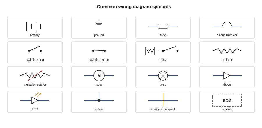
Symbols vary somewhat between manufacturers, but the common ones are similar. The battery is a set of long and short parallel lines. A ground is a short stack of horizontal lines or a triangle, often labeled with a ground point number such as G301. A fuse is a small S-shaped line or a rectangle with a line through it, labeled with its rating and position. A switch is a hinged line that breaks the circuit, drawn in its rest position, and a relay is a coil next to one or more switch contacts. Resistors are zigzags or rectangles, motors are circles with an M, lamps are circles with a cross or loop inside, and diodes are triangles pointing at a bar, showing the direction they let current pass.
Modules are drawn as boxes, often with only their relevant pins shown and a note such as "full module on page 8-14." A dashed box around several parts means they are inside one assembly, such as a switch pack or a door module. A dot where wires cross means they are joined at a splice; wires that cross without a dot are not connected. Splices themselves are often numbered, such as S218, and located on the component location pages, because a corroded splice buried in a harness can cause faults in several circuits that share it.
Wire colors, sizes and circuit numbers
Each wire on a diagram is labeled with its color, and often its size and a circuit number. Color codes are abbreviations, such as BK for black, RD for red, GN for green, YE or YL for yellow and VT or PU for violet or purple. A wire with a stripe or tracer has two codes, such as GN/WH for green with a white stripe. Abbreviations differ between manufacturers, and the legend at the front of the diagrams gives the exact set. Sizes are given in square millimeters or AWG, as in Lesson 4. Circuit numbers, when used, identify the circuit's function and stay the same from one end of the wire to the other, even if the color changes at a connector, which happens more often than apprentices expect.
# Decode wire labels from a diagram legend (abbreviations differ by manufacturer)
legend = {"BK": "black", "BN": "brown", "RD": "red", "OG": "orange", "YE": "yellow", "GN": "green",
          "BU": "blue", "VT": "violet", "WH": "white", "PK": "pink", "LG": "light green"}
labels = ["0.5 GN/WH", "2.5 RD", "0.35 VT/YE", "4.0 BK", "0.5 LG/BK"]
for lab in labels:
    size, codes = lab.split()
    parts = codes.split("/")
    text = legend[parts[0]] + (" with a " + legend[parts[1]] + " stripe" if len(parts) > 1 else "")
print(f"{lab:<11} -> {size} mm2, {text}")0.5 GN/WH -> 0.5 mm2, green with a white stripe 2.5 RD -> 2.5 mm2, red 0.35 VT/YE -> 0.35 mm2, violet with a yellow stripe 4.0 BK -> 4.0 mm2, black 0.5 LG/BK -> 0.5 mm2, light green with a black stripe
Power distribution and ground distribution
Two kinds of page are used on almost every diagnosis. The power distribution pages show how battery voltage reaches each fuse: which fuses are hot at all times, which are hot only with the ignition in run or accessory, and which are fed through relays controlled by a module. They also show the fusible links and main fuses upstream. When a load has no power, the power distribution pages show what must be working upstream of its fuse.
The ground distribution pages show which circuits share each ground point. If several apparently unrelated faults appear at once, such as a dim right tail lamp, a flickering license plate lamp and a rear wiper that runs slowly, the ground distribution page may show that all three share ground G401 in the left rear quarter panel. One repair there fixes all three. Marty calls the ground distribution pages "the most underused pages in the service information."
Connector views and component locations
Connector views, also called connector end views, show each connector's face with its pin numbers, the color of the wire in each cavity, and which side the view is from. The most common error in using them is reading the view from the wrong side: a view of the harness side of the connector, looking into the terminals, is a mirror image of what a technician sees from the back of the connector when back-probing. Kiran checks the label on the view, such as "harness side" or "component side," every time, and confirms the pin by its wire color before probing.
Component location pages and images show where each component, connector, splice and ground point is on the vehicle, often with a photo or drawing and a description such as "behind the right C-pillar trim, above the wheelhouse." Harness routing views show which harness passes where, which matters for a sliding door, whose harness has to move with the door through a flexible track at the bottom of the opening.
Turning a diagram into a test plan
Before she touches the van, Kiran reads the sliding door diagram from top to bottom. The door has its own control module mounted in the door, powered by a 30-amp fuse that is hot at all times and grounded at a ground point on the door's inner panel. The overhead switch and the fob requests do not wire to the door directly; they are inputs to the body control module, which sends an open or close command to the door module over a LIN network wire. Power, ground and the LIN wire all cross from the body into the door through the flexible harness in the lower track, through connector C510 at the body side and C511 at the door side.
From that, she writes a short test plan. First, does the door module have power and ground at its connector, measured under load? Second, does the body control module see the switch request, which the scan tool can show as a live data item? Third, does the LIN signal reach the door module? And because the door still works by hand, its motor and latch are probably fine; the fault is likely to be in power, ground or communication, and the track harness is the most likely place, because it flexes every time the door moves.
# Turn a diagram into test points: walk the circuit from power to ground (data from the diagram)
circuit = [
    ("battery + / main fuse", "B+"),
    ("fuse F42, 30 A, hot at all times", "B+"),
    ("connector C510 pin 1 (body side)", "B+"),
    ("connector C511 pin 1 (door side, after the track harness)", "B+"),
    ("door module pin 1, power", "B+"),
    ("door module pin 6, ground", "GND"),
    ("connector C511 pin 4", "GND"),
    ("connector C510 pin 4", "GND"),
    ("ground point G506, right B-pillar", "GND"),
]
measured = {"C511 pin 1 (door side, after the track harness)": 0.4}
for i, (point, side) in enumerate(circuit, 1):
    key = point.replace("connector ", "")
    note = f"  measured {measured[key]:.1f} V" if key in measured else ""
    expect = "about battery voltage" if side == "B+" else "under 0.1 V to battery -"
print(f"{i}. {point:<54} expect {expect}{note}")1. battery + / main fuse expect about battery voltage 2. fuse F42, 30 A, hot at all times expect about battery voltage 3. connector C510 pin 1 (body side) expect about battery voltage 4. connector C511 pin 1 (door side, after the track harness) expect about battery voltage measured 0.4 V 5. door module pin 1, power expect about battery voltage 6. door module pin 6, ground expect under 0.1 V to battery - 7. connector C511 pin 4 expect under 0.1 V to battery - 8. connector C510 pin 4 expect under 0.1 V to battery - 9. ground point G506, right B-pillar expect under 0.1 V to battery -
At the door, she back-probes the module's power and ground pins with the door commanded to open. The module has 0.4 volts on its power pin, against 12.5 volts at the battery. The power is getting lost somewhere between the fuse and the module. She back-probes C510 at the body side of the track harness: 12.4 volts. So the open is in the track harness itself, between C510 and C511. With the door closed, the wire works intermittently; with the door open, it fails. Inside the flexible conduit she finds the red power wire cracked through its copper where the harness bends most, a classic flex fatigue failure on a high-mileage van with a door that opens dozens of times a day.
The manufacturer's service information calls for the track harness to be replaced as an assembly rather than spliced, because a splice inside the flexing section would itself crack. Kiran orders the harness, Simone calls Erik with the estimate, and the replacement is a straightforward hour of trim removal and connector work. Afterwards Kiran checks the door's full operation, its pinch protection by placing a padded block in the opening, and the module's stored codes, and she runs the door relearn procedure the service information requires after a power loss.
Worked problem
Which side of the connector is the view?
A connector end view labeled "harness side, looking into the terminals" shows pin 1 at the top left. Kiran is back-probing the same connector from the wire side while it is still plugged into the module. Where is pin 1 from her view?
Show solution
- The view shows the face of the connector, where the terminals are.
- From the back, where the wires enter, left and right are swapped.
- So pin 1 appears at the top right from her position.
- She confirms it by the wire color shown for pin 1 before probing.
Answer: Top right from the wire side; confirm with the wire color.
When the diagram and the vehicle disagree
Occasionally the wire Kiran finds does not match the diagram: a different color, an extra splice or a connector that is not shown. Before deciding the diagram is wrong, she checks that she has the right diagram for the build date and options, and that nobody has modified the harness, which add-on accessories such as remote starters and trailer modules often do. If the vehicle is original and still does not match, she follows the wire physically, records what she finds, and tells the service information provider through its feedback link so that the next technician is not misled. Marty keeps a folder of such notes for the vehicles the shop sees most.
Common mistakes
MistakeAssuming the diagram's layout matches the vehicle's layout.
InsteadA diagram shows connections only; use the component location pages to find parts.
MistakeReading a connector view from the wrong side.
InsteadCheck whether the view is harness side or component side, and confirm pins by wire color.
MistakeIgnoring the ground distribution pages.
InsteadSeveral odd faults at once often share one ground point.
MistakeUsing a diagram for the wrong model year or option level.
InsteadCheck the VIN, build date and options before relying on it.
MistakeSplicing a harness that the manufacturer says must be replaced.
InsteadFollow the service information, especially in flexing sections.
Summary and key terms
- Wiring diagrams show electrical connections, usually with power at the top and ground at the bottom.
- Symbols, color codes and abbreviations are defined in each manufacturer's legend.
- Power distribution pages show how each fuse is fed; ground distribution pages show shared grounds.
- Connector views must be read from the correct side; confirm each pin by its wire color.
- Component location pages show where parts, connectors, splices and grounds are on the vehicle.
- A diagram turns into a test plan: power, ground, inputs, outputs and communication.
- Flexing harnesses, such as sliding door tracks, are common sites of open circuits.
- Wiring diagram
- A drawing that shows how the components of a circuit are electrically connected.
- Power distribution
- The diagram pages that show how battery voltage reaches each fuse.
- Ground distribution
- The diagram pages that show which circuits share each ground point.
- Connector end view
- A drawing of a connector face showing pin numbers and wire colors.
- Splice
- A point where several wires are joined inside a harness.
- Tracer
- A stripe of a second color on a wire's insulation.
- Component location
- A page or image that shows where a part is mounted on the vehicle.
Practice problems
Work each problem on paper first, then reveal the answer to check.
What does a dot where two wires cross on a diagram mean?
Show answer
The wires are joined at a splice.
Three faults appear at once in the rear of a vehicle. Which diagram page should be checked early?
Show answer
The ground distribution page, to see whether they share a ground.
Why check a wire's circuit number as well as its color?
Show answer
The color can change at a connector while the circuit number stays the same.
The door module has no power, but the body side of the track harness does. Where is the open?
Show answer
In the track harness between the two connectors.
Lesson quiz · 5 questions
Score 60% or more to complete this lesson.
Create a free account to save your progress, take quizzes and earn a certificate.