
ARCH-420 · Lesson 3 of 12 · 21 min
Plans, sections and details
Brandt opens the third week with a pencil sketch on the board: a long rectangle with six sawtooth peaks along its top, a slab under it and two short lines for the walls. It is Callum's makerspace, drawn the way architects draw it in the first ten minutes of design. Then he asks Callum to tell him, from that sketch, how far the glazing sits from the end of the roof tooth, what the flashing is made of, and where the rain goes. Callum laughs. The sketch does not say. Brandt's point is that every drawing answers a limited set of questions at its own scale, and a set works only if each question is answered somewhere, once, at a scale large enough to answer it properly. That chain from the whole to the part is the subject of this lesson.
The hierarchy of drawings
Construction drawings work from the general to the specific. Plans and elevations at small scale show the whole building and the relationships among its parts. Building sections cut through the whole to show heights and the relationships between floors. Wall sections at a larger scale show the assembly of a wall from foundation to roof. Details at the largest scale show how individual pieces meet. Each level carries only what it can show clearly and refers the reader to the next level for the rest. A plan at 1/8 inch to the foot can show that a wall exists, how long it is and which wall type it is, but it cannot show how the air barrier turns the corner at the window; that belongs in a detail at 3 inches to the foot or larger.
| Drawing | Typical scale | What it answers |
|---|---|---|
| Site plan | 1 in = 20 ft or 1 in = 40 ft | Where the building sits, grades, access, utilities |
| Floor plans | 1/8 in = 1 ft | Layout, walls, doors, dimensions, references |
| Reflected ceiling plans | 1/8 in = 1 ft | Ceiling heights and materials, lights, diffusers, sprinklers |
| Exterior elevations | 1/8 in = 1 ft | Openings, materials, heights, control joints |
| Building sections | 1/8 in = 1 ft | Floor-to-floor heights, roof slopes, vertical relationships |
| Enlarged plans | 1/4 in = 1 ft | Stairs, washrooms, kitchens, rooms with many fixtures |
| Wall sections | 3/4 in = 1 ft | The full assembly from footing to parapet |
| Details | 3 in = 1 ft or half full size | How the pieces meet, layer by layer |
Choosing the scale is a design decision. Too small, and the drawing cannot show what it must; too large, and the sheet fills with empty space and the set grows without adding information. Brandt adds that the scale must be chosen from the scales that the measuring tools of the trades use. Imperial drawings use the architect's scales, from 1/16 inch to 3 inches to the foot, and odd scales should be avoided because a site superintendent with a scale rule cannot read them.
Plans
A floor plan is a horizontal section cut through the building, by convention about 4 ft above the floor, looking down. Everything cut by the plane, such as walls, columns and window openings, is drawn with the heaviest lines; everything seen below the plane, such as floor patterns, casework and steps, is drawn lighter; and things above the plane that matter, such as the edge of the mezzanine or the beams of the roof teeth, are drawn dashed. The line weights are not decoration. They let a reader tell in a glance what is solid and what is beyond, and a plan drawn with every line at the same weight is much harder to read even when every line is correct.
On the plans the students learn to separate what each plan is for. The floor plans of the east wing will show walls, doors, windows, stairs, the grid of columns, wall type tags, door marks, room names and numbers, dimensions and the references to sections, elevations and details. They will not show furniture, ceiling lights or finish patterns, which belong on the furniture plan, the reflected ceiling plan and the finish plan or schedule. Crowding every kind of information onto one plan is a common student habit, and it produces plans in which nothing can be found.
Dimensions deserve their own rules. Brandt asks the team to dimension the east wing from the structural grid, because the grid is set out first on site and everything else is located from it. Strings of dimensions run from grid to grid, then from grid to the face of each wall or opening, with an overall dimension outside them. Each dimension states its reference: face of framing, face of finish or center line, with a general note saying which applies unless noted otherwise. Strings must close, so that the sum of the parts equals the overall, and no dimension should be stated twice. A plan that says a room is 20 ft in one place and 19 ft 9 in in another invites the contractor to pick the one that suits them.
Elevations, sections and wall sections
Exterior elevations show the building's faces: the openings, the materials, the joints and the heights of floors, roofs and parapets, measured from a datum such as the finished ground floor. On the east wing the north elevation is the most demanding, because the six roof teeth must be shown with their glazing, the flashing at each valley and the gutters and downspouts that carry the water away. Interior elevations, usually on the large-scale sheets, show walls with many items on them, such as the makerspace's tool wall and the washrooms.
Building sections cut through the whole building and show how the floors, roof and structure stack up, with floor-to-floor heights and roof slopes. Wall sections cut through one exterior wall at a larger scale and show every layer from the footing and the slab edge, through each floor, to the parapet or the eave, with the structure, insulation, air barrier, cladding and interior finishes labeled. In many offices the wall sections are where the building is really described; a contractor who wants to understand how the envelope works will go straight to them. Callum's wall sections for the east wing will cut through the north wall under a roof tooth, the south wall of the multipurpose wing and the brick base on the avenue.
Details show the places where the wall sections are too small to be clear: the head, sill and jamb of each window type, the valley of each roof tooth, the base of the wall at the slab, the parapet and the canopy connection. Brandt's advice is to draw a detail for every condition that is not obvious and not repeated elsewhere, and to resist the temptation to fill sheets with details copied from previous projects. A detail library is useful only if every detail is checked against this building, its materials and its dimensions. A standard detail of a parapet for a steel-stud wall placed in a set for a mass timber building is worse than no detail at all, because it looks authoritative.
References that lead the reader
The drawings are linked by reference symbols. A section cut on a plan is shown by a line with a symbol at each end: a circle divided horizontally, with the drawing number above the line and the sheet number below it, and an arrow or a filled triangle showing the direction of view. An elevation mark looks similar. A detail callout is a circle or a cloud around the area enlarged, connected by a leader to the same kind of bubble. On the target sheet, each drawing carries a title with the same bubble, its name and its scale.
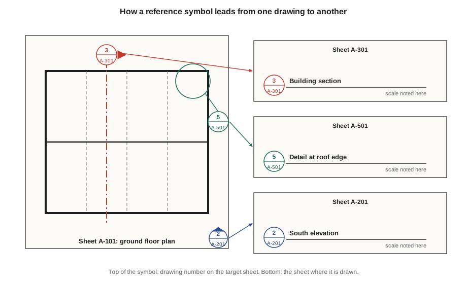
References only work if they are complete and correct in both directions. Every symbol on a plan must point to a drawing that exists on the sheet named, and every section, elevation and detail should be called out from somewhere, or the reader will never know which part of the building it describes. Broken references are among the most common errors in sets, usually because a drawing was moved to another sheet late in the job. Most modeling software now updates references automatically when a view is moved, but only for views that are placed through the software; a detail drawn as linework and labeled by hand will not update.
# Check that every reference symbol points to a drawing that exists, and that
# every drawing is referenced from somewhere.
drawings = {  # sheet -> drawing numbers placed on it
    "A-201": [1, 2], "A-301": [1, 2, 3], "A-311": [1, 2, 3, 4],
    "A-501": [1, 2, 3, 4, 5, 6, 7], "A-401": [1, 2],
}
references = [  # (from sheet, drawing number, target sheet)
    ("A-101", 3, "A-301"), ("A-101", 1, "A-301"), ("A-101", 2, "A-201"),
    ("A-101", 1, "A-311"), ("A-102", 2, "A-311"), ("A-102", 3, "A-311"),
    ("A-311", 4, "A-501"), ("A-311", 5, "A-501"), ("A-311", 6, "A-501"),
    ("A-301", 7, "A-501"), ("A-101", 1, "A-401"), ("A-311", 8, "A-501"),
]
broken = [(f, n, t) for f, n, t in references if n not in drawings.get(t, [])]
called = {(t, n) for f, n, t in references}
orphans = [(s, n) for s, ns in drawings.items() for n in ns if (s, n) not in called]
print("Broken references:")
for f, n, t in broken:
    print(f"  on {f}: {n}/{t} points to a drawing that does not exist")
print("Drawings never referenced:")
for s, n in sorted(orphans):
    print(f"  {n}/{s}")
print(f"{len(references)} references checked, {len(broken)} broken, {len(orphans)} orphans")Broken references: on A-311: 8/A-501 points to a drawing that does not exist Drawings never referenced: 1/A-201 2/A-301 4/A-311 2/A-401 1/A-501 2/A-501 3/A-501 12 references checked, 1 broken, 7 orphans
When the students run the check on their own early set, it finds a reference to a detail 8 on A-501 that does not exist and several details that nothing points to. Callum recognizes the orphans: they are details he drew for the first version of the roof teeth before the number of teeth was reduced from eight to six. They were never deleted, and in a real set they would have been priced.
Notes and keynotes
Drawings also carry words: room names, material labels and notes. Brandt asks for notes that are short, consistent with the specifications and written in the same terms. A label on a wall section should name the material generically, such as 'mineral wool insulation, 6 in', and leave the product, standard and installation to the specification section that covers it. Labels such as 'rigid insulation as per spec' are useless, because they neither describe the material nor say which section to read. Many offices use keynotes: short reference codes on the drawing, often tied to the specification section number, with a legend on each sheet giving the full text. Keynotes keep the drawings uncluttered and the terms consistent, at the cost of making the reader look up each note. Whichever system is used, it must be used the same way on every sheet.
Worked problem
Choosing the scale for the roof valley detail
The valley between two roof teeth, where the sloped metal roof meets the base of the next tooth's glazing, involves the CLT panel, a tapered insulation cricket, the membrane, the metal roofing, the gutter, the glazing sill and two flashings. At what scale should it be drawn, and why?
Show solution
- List what the detail must show: the layers of the roof, the gutter profile, the laps of the membrane and flashings, the sill of the glazing and the fasteners.
- Estimate the smallest dimension that matters: the lap of the flashing over the gutter, about 2 in.
- At 3/4 in = 1 ft that lap would be about 1/8 in on paper, too small to read clearly; at 3 in = 1 ft it is about 1/2 in, which is legible.
- Choose 3 in = 1 ft and check that the whole valley, about 4 ft across, fits a detail block on the sheet.
Answer: Draw it at 3 in = 1 ft, the scale at which the smallest dimension that matters can be read.
Exercise 3: following one element through the set
- Choose the north wall of the makerspace and list every drawing in the east wing set that should show it, from plan to detail.
- For each drawing, write the questions about the wall that it answers and those it leaves to the next drawing.
- Draw the reference symbols that link the drawings, and check that every link works in both directions.
- Write the labels for the wall section using generic material names that match the specification sections.
Self-check
- Does each drawing answer the questions its scale can answer, and refer the rest?
- Do my dimension strings close and state their reference faces?
- Does every reference point to an existing drawing, and is every drawing referenced?
- Are my notes generic, short and consistent with the specifications?
Common mistakes
MistakePutting every kind of information on one plan.
InsteadSeparate floor plans, ceiling plans, finish and furniture plans so each can be read.
MistakeDrawing details at too small a scale.
InsteadChoose the scale from the smallest dimension the detail must show.
MistakeCopying details from earlier projects without checking them.
InsteadCheck every library detail against this building's materials and dimensions.
MistakeLeaving broken or orphaned references.
InsteadCheck references in both directions at every issue.
MistakeWriting notes that refer vaguely to the specification.
InsteadName the material generically and let the specification section govern the product.
Summary and key terms
- Drawings work from the general to the specific, and each scale answers its own set of questions.
- Plans are horizontal cuts, drawn with line weights that separate what is cut from what is beyond.
- Dimensions run from the structural grid, state their reference faces and close.
- Wall sections and details carry the real description of the envelope and the joints.
- Reference symbols link drawings in both directions, and notes use the same terms as the specifications.
- Cut plane
- The imaginary horizontal plane, about 4 ft above the floor, at which a floor plan is cut.
- Wall section
- A large-scale section through an exterior wall showing every layer from the foundation to the roof.
- Detail
- A drawing at large scale of a specific joint or condition.
- Reference symbol
- A symbol that identifies a drawing by its number and the sheet on which it appears.
- Keynote
- A short code on a drawing that refers to a full note in a legend, often tied to a specification section.
Practice problems
Work each problem on paper first, then reveal the answer to check.
At what height is a floor plan conventionally cut?
Show answer
About 4 ft above the floor.
What does a section symbol labeled 3 over A-301 tell the reader?
Show answer
That the section is drawing 3 on sheet A-301.
Why should dimension strings close?
Show answer
So the parts add up to the overall dimension and no conflicting dimensions exist.
Why is a detail copied from another project risky?
Show answer
It may not match this building's materials or dimensions but looks authoritative, so it may be priced and built.
What is an orphaned drawing?
Show answer
A drawing in the set that no reference symbol points to, so the reader cannot tell where it applies.
Lesson quiz · 5 questions
Score 60% or more to complete this lesson.
Create a free account to save your progress, take quizzes and earn a certificate.